

He already promised me he'd make it to JapshowKawa wrote:Rob, you are a godLooking forward to seeing it this year.
Yeah, yeah, yeahindigolemon wrote:Can't wait to see it in the flesh (deffo gonna try for some shows this year)
Congratulations to vtecmec for winning May/June's Lude Of The Month, with his DIY Turbo BB1 build.
>>> Click Here For Profile <<<

>>> Click Here For Profile <<<
Supercharged Mugen Lude (03/06/14 Update!)
-
indigolemon

- The Chaos Engine
- Posts: 6682
- Joined: Wed Jun 30, 2010 1:45 pm
- My Generation: 4G
- PSN GamerTag: M149YSL
- Location: Kelty, Fife
- Has thanked: 24 times
- Been thanked: 71 times
- Contact:
I will be there!JayJay wrote:He already promised me he'd make it to JapshowKawa wrote:Rob, you are a god
Yeah, yeah, yeahindigolemon wrote:Can't wait to see it in the flesh (deffo gonna try for some shows this year)

'On two occasions I have been asked, 'Pray, Mr. Babbage, if you put into the machine wrong figures, will the right answers come out?' I am not able rightly to apprehend the kind of confusion of ideas that could provoke such a question.' - Charles Babbage
-
nucleustylzlude

- Moderator
- Posts: 4013
- Joined: Wed Aug 11, 2010 11:46 pm
- My Generation: 4G
- Location: Bristol, UK!
- Been thanked: 7 times
- Contact:
 Re: Supercharged Mugen Lude
You should all be there! 
But I may not???
We'll see.
Cheers Terry - progress still a little slow, but Rome wasn't built in a day!
Got me some more goodies too!
But I may not???
We'll see.
Cheers Terry - progress still a little slow, but Rome wasn't built in a day!
Got me some more goodies too!

-
indigolemon
- The Chaos Engine
- Posts: 6682
- Joined: Wed Jun 30, 2010 1:45 pm
- My Generation: 4G
- PSN GamerTag: M149YSL
- Location: Kelty, Fife
- Has thanked: 24 times
- Been thanked: 71 times
- Contact:
None of that! If I'm driving all the way down I want to see all the kickass ludes on this forum in the fleshnucleustylzlude wrote:You should all be there!
But I may not???
We'll see.
'On two occasions I have been asked, 'Pray, Mr. Babbage, if you put into the machine wrong figures, will the right answers come out?' I am not able rightly to apprehend the kind of confusion of ideas that could provoke such a question.' - Charles Babbage

-
nucleustylzlude
- Moderator
- Posts: 4013
- Joined: Wed Aug 11, 2010 11:46 pm
- My Generation: 4G
- Location: Bristol, UK!
- Been thanked: 7 times
- Contact:
BUILD PART 4) - Parts (Cont'd) - Miscellaneous
BUILD PART 4) – Parts (Continued)
Miscellaneous
Polyurethane motor mounts
I have a set of Energy Suspension polyurethane engine mount inserts:
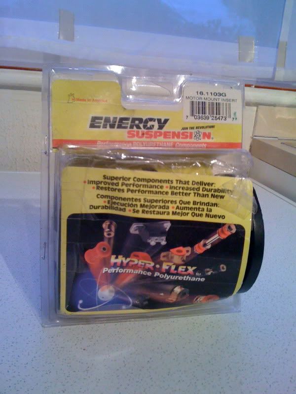
What do they do? Well, in their words, ‘in performance conditions, they will help to reduce wheel hop and traction loss. In addition they also reduce torque induced movement that can actually damage vehicle components.’
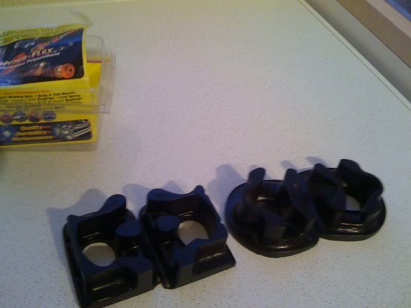
While I will benefit from these performance related features, they are also being fitted for a practical reason. One of the difficulties in fitting the 5th gen JRSC to a 4th gen as explained in an earlier update is the two areas of concern: 1) The shock tower corner and 2) the strut mount/allen bolt that projects up. As the engine torques back through the movement of the engine mounts, it has been found that the pulley on the jackshaft and belt can rub against the top of the mount area. Potentially damaging the pulley, or worse, fraying or breaking the belt. These mounts will help to reduce this movement, thus reducing this clearance issue. I will also be filing down and protecting the mount top, and if movement is still evident, possibly fit an engine torque damper.
The main downside of fitting motor mount inserts is the transfer of the engines shakes/vibrations to the rest of the car. These would normally be absorbed by the softer OEM engine mounts. Some experience the dash shaking a little, and other similar issues. Nothing I’m particularly bothered about for the gains I’ll see and the fitment issues.
Ignition – colder spark plugs
When increasing the pressure and heat within the combustion chamber, as part of any Turbo or Supercharger build you will also need to source a new set of spark plugs that have a colder heat range. The colder plug will help to reduce detonation. Our standard ludes run a heat range of 6 (NGK heat range reference – Denso and others are different), so I will be stepping up to a heat range of 7. Some large builds go colder again. The standard spark plugs for our 2.2 VTEC Preludes as per the manual are:
NGK Platinum Plugs = PZFR6F-11
These are a platinum plug, but a lot of people, including me, like to run the Iridium equivalent:
Denso = IK20
NGK = ZFR6FIX-11
I will be moving back to a standard platinum plug with a cooler NGK heat range of 7, as follows:
NGK = PFR7G-11
Denso Iridium option = IK22
Or may even consider a set of copper plugs (ZFR7F-11) as they are cheap for the following use…
It is helpful to buy a spare set at the beginning as they can foul during the initial tuning session to get the car running at a suitable air/fuel ratio. Turbo builds especially with big power and new newly built blocks to be broken in.
Only other thing I need to investigate is the spark plug electrode gap. I know they are pre-gapped, but to standard spec. With a hotter boosted chamber less spark should be needed to combust in theory. I may pick up the phone to Rich at PAW to get his views on this nearer the time.
Nothing more on the ignition side of things, I already have my Nology hotwire leads which are still fairly new and seem to work very well. The remaining Honda ignition system is supposed to be very good and more than capable for my power goals.
Cam/timing belt change / Manual Tensioner Conversion / Seals / Oil change
The car has been in my possession for 7 years and it was on 62k when I bought it and had the full cambelt change/service at a Honda dealership completed. She is coming up to a special birthday of 100k miles soon and while I could run it a little longer, the 7 year interval of low miles is enough for me to want to change the belt again. I will be pushing the factory tolerances and do not want a snapped cambelt causing damage at my maintenance negligence.
So if I can get the barsteward of a crank bolt off, then I’m going all out to do the belt change myself. Including changing out the hydraulic auto tensioner to the H23 manual tensioner.
While at Japshow last year, I was bestowed the great and awesome PUK relic that is the BEAST CRANK PULLEY HOLDER. Passed through the ranks it is worth it’s weight in gold – and trust me it weighs a ton!
Here’s old bessy:
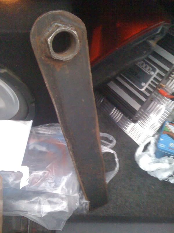
Once I’m done – not sure who wants it back – Si is it? Or pass it on to the next trusted candidate?
I’ll try and take as many pics as possible during this procedure – including setting up all items for correct timing – balancer shafts, cams, crank and finally timing with a strobe light and the dizzy.
However, I do have this very handy and detailed how-to as a download Word document – should help out a lot of people:
http://www.nucleuscreations.co.uk/timin ... 0ready.doc
It has some other bits and pieces in there too.
H23 Manual Tensioner Conversion for the H22
So why use the H23 manual tensioner conversion?
In a nutshell, they are prone to failure, especially when undertaking large engine builds/increasing considerable power/higher rpms. There could be a whole thread dedicated to people’s views and experiences on this. But just type into the search engine of choice, ‘Prelude auto tensioner fail’ and you’ll find enough reasons to remove it.
The manual one from the H23 motor, in theory will never fail as there is not a ‘sealed working’ component like the auto tensioner that can fail in such a way (tensioner bearing life to one side). It essentially simplifies the belt tensioning device, but transfers the responsibility of correct belt tension to the installer. They are extremely tight to get on, so the amount you need to increase tension after a run-in isn’t much, if at all.
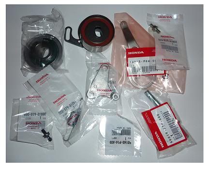
What parts do I need for the H23 manual tensioner conversion?
Many people list the parts on various sites, but some list a couple of items which really aren’t required. Here is all you need (My Description – Honda Description – Part No – Approx price):
1) H23 Balancer belt tensioner - BALANCER BELT ADJUSTER - 13404-PT0-004 - £80 from Honda! (cheaper from other car parts places – Koyo bearing)
2) H23 Cambelt tensioner - TIMING BELT ADJUSTER - 14510-PT0-004 - £40-£70 from Honda! (cheaper from other car parts places – Koyo bearing)
3) H23 Cambelt tensioner spring - TIMING BELT ADJUSTER SPRING - 14516-PT2-000 - £5.50 (Honda only!)
4) H23 Small Retainer Bolt for H23 Tensioner to rotate against - TIMING BELT ADJUSTER BASE BOLT - 90014-P14-A00 - £4 (Honda only!)
5) H23 Small Retainer Bolt for H23 Spring to mount to (other side of spring hooks onto tensioner) - TIMING BELT ADJUSTER SPRING BOLT - 90015-PT0-000 - £8 (Honda only!)
6) Long bolt that the two tensioners are slotted onto (and tighten/loosen for tensioning) - TIMING BELT ADJUSTER BOLT - 90016-PT0-000 - £10 (Honda only!)
7) Washer for the base of the bolt above - WASHER, PLAIN (11MM) - 90140-P14-A0 - £3.50 (Honda only! Well you can probably find a cheaper alternative)
That’s your lot. For information, the other two items that some people also list are as follows:
1) BALANCER BELT ADJUSTER BRACKET - 13415-PT0-000 - £8 (H22 arm is re-used, same part)
2) ADJUSTER PLATE - 14521-P14-A00 - £15 (Can be added as a pivot point for the H23 tensioner arm, there’s no harm in doing so. But how tight the belt is usually doesn’t need adjusting much, if at all. So the travel of the pivot doesn’t really get used)
The conversion utilises the H23 cam/timing belt tensioner bearing and the H23 balancer belt tensioner bearing, but uses the H22s belts for both items. It’s the diameter of the H23 cam/timing belt tensioner that is larger than the H22s which keeps the belt very tight from the minute you manage to get it on (It can be a PITA to slip onto the cams). The H23 balancer belt tensioner is actually the same diameter as the H22s but the back of it has a spacer ‘built-in’ which keeps the clearances correct so it does not rub/catch on the H23 timing/cam belt tensioner.
However, if like me you happen to have a new H22 balancer belt tensioner bearing – don’t throw it away. You can utilise this instead of having to buy the H23 item by adding some large diameter spacer washers to make the clearance. I’ll add the exact dimensions of the washer/s required when I get to the installation write-up.
So that’s it on the H23 manual tensioner conversion. I’ll do a full write-up in this build for people to follow suit.
In the mean while, here is probably the best two how-tos online: http://www.preludepower.com/forums/show ... p?t=229140
http://mr22.tistory.com/tag/tensioner
Seals/water pump
While the cambelt and crank pulley is off, I intend to replace the water pump and main seals on the cam side of the engine, including both cam seals, crank seal, front balance shaft ring seal (and add retainer if I don’t have one) & the rear balance shaft ring gear seal. Likewise, I forgot to add in my transmission section a new rear (being clutch side) main oil seal too!
Here are the part nos for reference (My Description – Honda Description – Part No – Approx price):
1) Cam oil seals (gear side) - OIL SEAL, 29X43X8 (NOK) or Arai) - 91213-PR3-003 or 004 - £7 each (2no required per cam!)
2) Crank Oil Seal - Oil pump side - OIL SEAL, 40X52X7 (ARAI) - 91212-P0A-004 or -PT0-003 - £13.50
3) Balance Shaft Seal - front of engine - OIL SEAL, 27X40X8 (NOK) - 91233-PT0-003 - £10.5
4) Balance Shaft Seal Retainer - Honda maintenance addition - stops seal rise - ???Honda Description - 06923-P0A-306 - £3
5) Rear Balance Shaft Ring Gear Seal - PACKING B, OIL PUMP (ARAI) - 15114-PT0-003 - £4
Unsure at this point whether I need to replace the crank pulley bolt & key??? I’ll confirm this and edit.
May not sound a lot – but add up all the seals and tensioner parts and it’s quite a few £££’s! Worth doing though!
Oil Change
No major info to give you all really – just another oil change! It’s been sat in the garage over winter, not hugely dirty oil, but I will do this for general maintenance and to give the new setup every little bit of love and attention. Nothing fancy on the filter or oil choice ether TBH. I’ve used FRAM filters with Magnatec for a while now and it’s done no harm – engine has always made good power (for a UK model too might I add). I already added a magnetic drain bolt on the last change, so will give this an inspection and clean up. I’ll also be adding the oil pressure sensor to my filter sandwich plate – which already has an oil temp one threaded in – see below for more on gauges.
Gauges
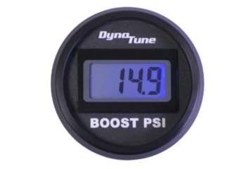
Dyno Tune Boost Gauge
 Dyno Tune Site Info
This was yet another ebay bargain. Gotta have a boost gauge when boosting. Even more so on the setup I am going for. This gauge as they put it is, ‘the smallest, lightest, most accurate Boost pressure Gauge available’! Can’t say fairer than that.
With supercharger setups, various things can effect the boost levels, such as belt slippage and airflow mods. I have a Motorvations pulley as so:
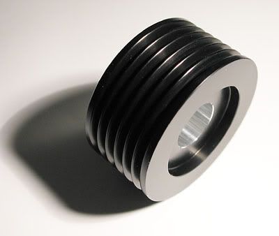
This is an increased size from the Jackson Racing pulley (1.75” up to 2.0” from memory), which sits on the charger side of the jackshaft, see here:
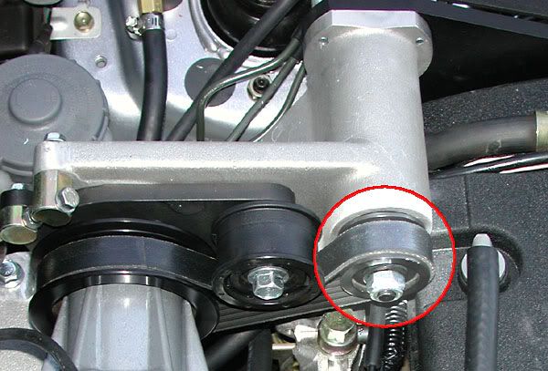
This pulley has been shown to increase boost levels from 6psi to 9psi. Various people struggle to exceed 7psi if there belt slips on the pulleys – making tuning a bit of a pain. There is also an Accord crank pulley which produces the same result (6 to 9psi), which I also have a new one from Honda! But the main area of belt slippage comes from the smaller jackshaft side belt. I already have an additional roller pulley on the main pulley holder to keep the longer serpentine belt tight. The Motorvations pulley is better though as it increases the size in a way that also increases the tension against the adjuster. So fingers crossed my setup will produce a clean 9psi at some point in the rev range and this gauge will very accurately tell me so.
Just a note to say that if the airflow of a roots blower is improved, e.g. port and polish of the intake mani and head – you will see an increase in power and a drop in boost levels – WIN/WIN situation. Look further on for some minor mods to this affect.
AEM Uego Wideband
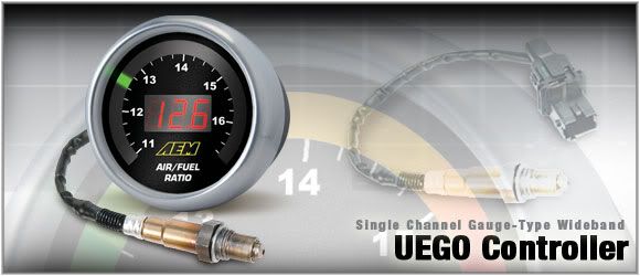
AEM site info
A wideband Lambda sensor is more of an essential item for tuning purposes to adjust the fuel/ignition parameters to achieve an acceptable air/fuel ratio and find a power compromise. But very handy, if you want to do some mild tuning yourselves (street tune) – like I will no doubt have a dabble with.
It is also a great reading to keep an eye on the health of your engine. If something goes a miss and you have too much or a lack of fuel or air for whatever reason – this will flag it up straight away. And hopefully before any damage is done.
The AEM one is particularly good as it is self-calibrating and can be hooked up to my Hondata S300 through one of the option wires – probably use the A/C pin, which will enable me to datalog the readings for certain periods.
Literally just received this from the states.
£122 delivered.
Autometer Oil pressure
No pic to hand.
More important than the oil temp below, the oil pressure is vital to keep an eye on your engines running and health. A significant drop in oil pressure and your looking at a lot of headaches!
It is also a helper to know when your engine is up to optimum operating point – VTEC all the waaaaaay!!!!
Jackson Racing (essentially made by Autometer) oil temperature
I already had this item along with a Jackson Racing basic air/fuel ratio gauge.
Nothing much to explain on this one – it tells me the oil temp!
Just another good reading to be mindful of – good to know along with the pressure when the engine is actually at optimum operating temp before VTECing everywhere!
It will help me flag up if anything goes amiss on the temp side of things – coolant leak, etc.
Please Note: with the new AEM wideband, my old Jackson Racing air/fuel ratio will be removed and up for sale – which is a narrow band which runs off of the Honda OEM Lambda/O2 sensor. Not accurate enough for tuning purposes but a good indicator for any serious running issues. Heads up if anyone wants dibs.
DIY Bore & Polishing Work
While I have the intake manifold and gubbins off to get to my brake setup, I hope to freshen things up and improve the airflow a little better for my setup.
I’ll be giving all the parts a clean up and fresh lick of paint – top secret colour though!
But also have some DIY modification which should hopefully benefit my supercharger setup – mainly in the form of boring out the flow capacity of certain items/areas and then finishing them off to a smooth polished finish. Unlike a N/A setup, the purpose of a rough finish to create a certain airflow won’t be as affective on my setup in comparison to increasing volume. Of course this is my theory from reading around on the subject – a real bench flow test would prove all but not in my budget.
Throttle body
The 4th gen Preludes throttle body has a 62mm diameter opening. A great option is to replace the item for a larger aftermarket throttle body to increase the volume of air allowed to pass through to the intake. But this is a budget build after all now! Plus most aftermarket TB’s will lose you your FITV (fast idle throttle valve), which makes cold starts a bit trickier – low idle until engine has warmed up enough.
So the answer is to modify the OEM throttle body by boring out both sides of the butterfly so they taper in and out. This may seem restrictive, but airflow actually travels very successfully in this way – look at large exhaust collector designs.
Supercharger inlet pipe adaptor
In addition the SC intake pipe adaptor that mates the TB to the supercharger inlet has a throttle body opening side of 64mm. A poor choice by Jackson Racing creating a lip for the airflow. But gives a target to aim close to for the TB taper into the SC intake pipe. Some people in the states have done this mod on their SC setups with good results.
Supercharger plenum / lower intake manifold
I’ll also be working the lower part of the inlet manifold, boring & polishing the SC 8 runner holes of the intake. I may even open up the runners into 4 runners only. The supercharger plenum sits on this and will matched to the same work, with a taper into the openings + remove casting marks in plenum & polish too
Head
I may give the head inlet and outlet ports a good clean up and decoke. Maybe stretch to smoothing out some castings.
Weight Reduction
Along with increasing the power of my Preludes engine, I will also be (and have started) to reduce the overall weight of my BB1 Prelude to create a good compromise of power to weight ratio. Here is the list of things:
Remove Air Conditioning System (started)
Remove ABS
Remove PAS
Remove 4WS
Remove resonator solenoid / airbox bits (removed)
Remove EGR components (started)
Remove remaining SRS system parts
Remove sound proofing Relocate cruise
Relocate smaller battery to boot
Relocate cruise control actuator under dash
Well not too much pics and more listing of final bits of my plans. Good news is I’ve started some work but I’ll leave that for the next update.
Cheers,
Rob
Miscellaneous
Polyurethane motor mounts
I have a set of Energy Suspension polyurethane engine mount inserts:
What do they do? Well, in their words, ‘in performance conditions, they will help to reduce wheel hop and traction loss. In addition they also reduce torque induced movement that can actually damage vehicle components.’
While I will benefit from these performance related features, they are also being fitted for a practical reason. One of the difficulties in fitting the 5th gen JRSC to a 4th gen as explained in an earlier update is the two areas of concern: 1) The shock tower corner and 2) the strut mount/allen bolt that projects up. As the engine torques back through the movement of the engine mounts, it has been found that the pulley on the jackshaft and belt can rub against the top of the mount area. Potentially damaging the pulley, or worse, fraying or breaking the belt. These mounts will help to reduce this movement, thus reducing this clearance issue. I will also be filing down and protecting the mount top, and if movement is still evident, possibly fit an engine torque damper.
The main downside of fitting motor mount inserts is the transfer of the engines shakes/vibrations to the rest of the car. These would normally be absorbed by the softer OEM engine mounts. Some experience the dash shaking a little, and other similar issues. Nothing I’m particularly bothered about for the gains I’ll see and the fitment issues.
Ignition – colder spark plugs
When increasing the pressure and heat within the combustion chamber, as part of any Turbo or Supercharger build you will also need to source a new set of spark plugs that have a colder heat range. The colder plug will help to reduce detonation. Our standard ludes run a heat range of 6 (NGK heat range reference – Denso and others are different), so I will be stepping up to a heat range of 7. Some large builds go colder again. The standard spark plugs for our 2.2 VTEC Preludes as per the manual are:
NGK Platinum Plugs = PZFR6F-11
These are a platinum plug, but a lot of people, including me, like to run the Iridium equivalent:
Denso = IK20
NGK = ZFR6FIX-11
I will be moving back to a standard platinum plug with a cooler NGK heat range of 7, as follows:
NGK = PFR7G-11
Denso Iridium option = IK22
Or may even consider a set of copper plugs (ZFR7F-11) as they are cheap for the following use…
It is helpful to buy a spare set at the beginning as they can foul during the initial tuning session to get the car running at a suitable air/fuel ratio. Turbo builds especially with big power and new newly built blocks to be broken in.
Only other thing I need to investigate is the spark plug electrode gap. I know they are pre-gapped, but to standard spec. With a hotter boosted chamber less spark should be needed to combust in theory. I may pick up the phone to Rich at PAW to get his views on this nearer the time.
Nothing more on the ignition side of things, I already have my Nology hotwire leads which are still fairly new and seem to work very well. The remaining Honda ignition system is supposed to be very good and more than capable for my power goals.
Cam/timing belt change / Manual Tensioner Conversion / Seals / Oil change
The car has been in my possession for 7 years and it was on 62k when I bought it and had the full cambelt change/service at a Honda dealership completed. She is coming up to a special birthday of 100k miles soon and while I could run it a little longer, the 7 year interval of low miles is enough for me to want to change the belt again. I will be pushing the factory tolerances and do not want a snapped cambelt causing damage at my maintenance negligence.
So if I can get the barsteward of a crank bolt off, then I’m going all out to do the belt change myself. Including changing out the hydraulic auto tensioner to the H23 manual tensioner.
While at Japshow last year, I was bestowed the great and awesome PUK relic that is the BEAST CRANK PULLEY HOLDER. Passed through the ranks it is worth it’s weight in gold – and trust me it weighs a ton!
Here’s old bessy:
Once I’m done – not sure who wants it back – Si is it? Or pass it on to the next trusted candidate?
I’ll try and take as many pics as possible during this procedure – including setting up all items for correct timing – balancer shafts, cams, crank and finally timing with a strobe light and the dizzy.
However, I do have this very handy and detailed how-to as a download Word document – should help out a lot of people:
http://www.nucleuscreations.co.uk/timin ... 0ready.doc
It has some other bits and pieces in there too.
H23 Manual Tensioner Conversion for the H22
So why use the H23 manual tensioner conversion?
In a nutshell, they are prone to failure, especially when undertaking large engine builds/increasing considerable power/higher rpms. There could be a whole thread dedicated to people’s views and experiences on this. But just type into the search engine of choice, ‘Prelude auto tensioner fail’ and you’ll find enough reasons to remove it.
The manual one from the H23 motor, in theory will never fail as there is not a ‘sealed working’ component like the auto tensioner that can fail in such a way (tensioner bearing life to one side). It essentially simplifies the belt tensioning device, but transfers the responsibility of correct belt tension to the installer. They are extremely tight to get on, so the amount you need to increase tension after a run-in isn’t much, if at all.
What parts do I need for the H23 manual tensioner conversion?
Many people list the parts on various sites, but some list a couple of items which really aren’t required. Here is all you need (My Description – Honda Description – Part No – Approx price):
1) H23 Balancer belt tensioner - BALANCER BELT ADJUSTER - 13404-PT0-004 - £80 from Honda! (cheaper from other car parts places – Koyo bearing)
2) H23 Cambelt tensioner - TIMING BELT ADJUSTER - 14510-PT0-004 - £40-£70 from Honda! (cheaper from other car parts places – Koyo bearing)
3) H23 Cambelt tensioner spring - TIMING BELT ADJUSTER SPRING - 14516-PT2-000 - £5.50 (Honda only!)
4) H23 Small Retainer Bolt for H23 Tensioner to rotate against - TIMING BELT ADJUSTER BASE BOLT - 90014-P14-A00 - £4 (Honda only!)
5) H23 Small Retainer Bolt for H23 Spring to mount to (other side of spring hooks onto tensioner) - TIMING BELT ADJUSTER SPRING BOLT - 90015-PT0-000 - £8 (Honda only!)
6) Long bolt that the two tensioners are slotted onto (and tighten/loosen for tensioning) - TIMING BELT ADJUSTER BOLT - 90016-PT0-000 - £10 (Honda only!)
7) Washer for the base of the bolt above - WASHER, PLAIN (11MM) - 90140-P14-A0 - £3.50 (Honda only! Well you can probably find a cheaper alternative)
That’s your lot. For information, the other two items that some people also list are as follows:
1) BALANCER BELT ADJUSTER BRACKET - 13415-PT0-000 - £8 (H22 arm is re-used, same part)
2) ADJUSTER PLATE - 14521-P14-A00 - £15 (Can be added as a pivot point for the H23 tensioner arm, there’s no harm in doing so. But how tight the belt is usually doesn’t need adjusting much, if at all. So the travel of the pivot doesn’t really get used)
The conversion utilises the H23 cam/timing belt tensioner bearing and the H23 balancer belt tensioner bearing, but uses the H22s belts for both items. It’s the diameter of the H23 cam/timing belt tensioner that is larger than the H22s which keeps the belt very tight from the minute you manage to get it on (It can be a PITA to slip onto the cams). The H23 balancer belt tensioner is actually the same diameter as the H22s but the back of it has a spacer ‘built-in’ which keeps the clearances correct so it does not rub/catch on the H23 timing/cam belt tensioner.
However, if like me you happen to have a new H22 balancer belt tensioner bearing – don’t throw it away. You can utilise this instead of having to buy the H23 item by adding some large diameter spacer washers to make the clearance. I’ll add the exact dimensions of the washer/s required when I get to the installation write-up.
So that’s it on the H23 manual tensioner conversion. I’ll do a full write-up in this build for people to follow suit.
In the mean while, here is probably the best two how-tos online: http://www.preludepower.com/forums/show ... p?t=229140
http://mr22.tistory.com/tag/tensioner
Seals/water pump
While the cambelt and crank pulley is off, I intend to replace the water pump and main seals on the cam side of the engine, including both cam seals, crank seal, front balance shaft ring seal (and add retainer if I don’t have one) & the rear balance shaft ring gear seal. Likewise, I forgot to add in my transmission section a new rear (being clutch side) main oil seal too!
Here are the part nos for reference (My Description – Honda Description – Part No – Approx price):
1) Cam oil seals (gear side) - OIL SEAL, 29X43X8 (NOK) or Arai) - 91213-PR3-003 or 004 - £7 each (2no required per cam!)
2) Crank Oil Seal - Oil pump side - OIL SEAL, 40X52X7 (ARAI) - 91212-P0A-004 or -PT0-003 - £13.50
3) Balance Shaft Seal - front of engine - OIL SEAL, 27X40X8 (NOK) - 91233-PT0-003 - £10.5
4) Balance Shaft Seal Retainer - Honda maintenance addition - stops seal rise - ???Honda Description - 06923-P0A-306 - £3
5) Rear Balance Shaft Ring Gear Seal - PACKING B, OIL PUMP (ARAI) - 15114-PT0-003 - £4
Unsure at this point whether I need to replace the crank pulley bolt & key??? I’ll confirm this and edit.
May not sound a lot – but add up all the seals and tensioner parts and it’s quite a few £££’s! Worth doing though!
Oil Change
No major info to give you all really – just another oil change! It’s been sat in the garage over winter, not hugely dirty oil, but I will do this for general maintenance and to give the new setup every little bit of love and attention. Nothing fancy on the filter or oil choice ether TBH. I’ve used FRAM filters with Magnatec for a while now and it’s done no harm – engine has always made good power (for a UK model too might I add). I already added a magnetic drain bolt on the last change, so will give this an inspection and clean up. I’ll also be adding the oil pressure sensor to my filter sandwich plate – which already has an oil temp one threaded in – see below for more on gauges.
Gauges
Dyno Tune Boost Gauge
Dyno Tune Site InfoThis was yet another ebay bargain. Gotta have a boost gauge when boosting. Even more so on the setup I am going for. This gauge as they put it is, ‘the smallest, lightest, most accurate Boost pressure Gauge available’! Can’t say fairer than that.
With supercharger setups, various things can effect the boost levels, such as belt slippage and airflow mods. I have a Motorvations pulley as so:
This is an increased size from the Jackson Racing pulley (1.75” up to 2.0” from memory), which sits on the charger side of the jackshaft, see here:
This pulley has been shown to increase boost levels from 6psi to 9psi. Various people struggle to exceed 7psi if there belt slips on the pulleys – making tuning a bit of a pain. There is also an Accord crank pulley which produces the same result (6 to 9psi), which I also have a new one from Honda! But the main area of belt slippage comes from the smaller jackshaft side belt. I already have an additional roller pulley on the main pulley holder to keep the longer serpentine belt tight. The Motorvations pulley is better though as it increases the size in a way that also increases the tension against the adjuster. So fingers crossed my setup will produce a clean 9psi at some point in the rev range and this gauge will very accurately tell me so.
Just a note to say that if the airflow of a roots blower is improved, e.g. port and polish of the intake mani and head – you will see an increase in power and a drop in boost levels – WIN/WIN situation. Look further on for some minor mods to this affect.
AEM Uego Wideband
AEM site info
A wideband Lambda sensor is more of an essential item for tuning purposes to adjust the fuel/ignition parameters to achieve an acceptable air/fuel ratio and find a power compromise. But very handy, if you want to do some mild tuning yourselves (street tune) – like I will no doubt have a dabble with.
It is also a great reading to keep an eye on the health of your engine. If something goes a miss and you have too much or a lack of fuel or air for whatever reason – this will flag it up straight away. And hopefully before any damage is done.
The AEM one is particularly good as it is self-calibrating and can be hooked up to my Hondata S300 through one of the option wires – probably use the A/C pin, which will enable me to datalog the readings for certain periods.
Literally just received this from the states.
£122 delivered.
Autometer Oil pressure
No pic to hand.
More important than the oil temp below, the oil pressure is vital to keep an eye on your engines running and health. A significant drop in oil pressure and your looking at a lot of headaches!
It is also a helper to know when your engine is up to optimum operating point – VTEC all the waaaaaay!!!!
Jackson Racing (essentially made by Autometer) oil temperature
I already had this item along with a Jackson Racing basic air/fuel ratio gauge.
Nothing much to explain on this one – it tells me the oil temp!
Just another good reading to be mindful of – good to know along with the pressure when the engine is actually at optimum operating temp before VTECing everywhere!
It will help me flag up if anything goes amiss on the temp side of things – coolant leak, etc.
Please Note: with the new AEM wideband, my old Jackson Racing air/fuel ratio will be removed and up for sale – which is a narrow band which runs off of the Honda OEM Lambda/O2 sensor. Not accurate enough for tuning purposes but a good indicator for any serious running issues. Heads up if anyone wants dibs.
DIY Bore & Polishing Work
While I have the intake manifold and gubbins off to get to my brake setup, I hope to freshen things up and improve the airflow a little better for my setup.
I’ll be giving all the parts a clean up and fresh lick of paint – top secret colour though!
But also have some DIY modification which should hopefully benefit my supercharger setup – mainly in the form of boring out the flow capacity of certain items/areas and then finishing them off to a smooth polished finish. Unlike a N/A setup, the purpose of a rough finish to create a certain airflow won’t be as affective on my setup in comparison to increasing volume. Of course this is my theory from reading around on the subject – a real bench flow test would prove all but not in my budget.
Throttle body
The 4th gen Preludes throttle body has a 62mm diameter opening. A great option is to replace the item for a larger aftermarket throttle body to increase the volume of air allowed to pass through to the intake. But this is a budget build after all now! Plus most aftermarket TB’s will lose you your FITV (fast idle throttle valve), which makes cold starts a bit trickier – low idle until engine has warmed up enough.
So the answer is to modify the OEM throttle body by boring out both sides of the butterfly so they taper in and out. This may seem restrictive, but airflow actually travels very successfully in this way – look at large exhaust collector designs.
Supercharger inlet pipe adaptor
In addition the SC intake pipe adaptor that mates the TB to the supercharger inlet has a throttle body opening side of 64mm. A poor choice by Jackson Racing creating a lip for the airflow. But gives a target to aim close to for the TB taper into the SC intake pipe. Some people in the states have done this mod on their SC setups with good results.
Supercharger plenum / lower intake manifold
I’ll also be working the lower part of the inlet manifold, boring & polishing the SC 8 runner holes of the intake. I may even open up the runners into 4 runners only. The supercharger plenum sits on this and will matched to the same work, with a taper into the openings + remove casting marks in plenum & polish too
Head
I may give the head inlet and outlet ports a good clean up and decoke. Maybe stretch to smoothing out some castings.
Weight Reduction
Along with increasing the power of my Preludes engine, I will also be (and have started) to reduce the overall weight of my BB1 Prelude to create a good compromise of power to weight ratio. Here is the list of things:
Remove Air Conditioning System (started)
Remove ABS
Remove PAS
Remove 4WS
Remove resonator solenoid / airbox bits (removed)
Remove EGR components (started)
Remove remaining SRS system parts
Remove sound proofing Relocate cruise
Relocate smaller battery to boot
Relocate cruise control actuator under dash
Well not too much pics and more listing of final bits of my plans. Good news is I’ve started some work but I’ll leave that for the next update.
Cheers,
Rob
-
nucleustylzlude
- Moderator
- Posts: 4013
- Joined: Wed Aug 11, 2010 11:46 pm
- My Generation: 4G
- Location: Bristol, UK!
- Been thanked: 7 times
- Contact:
BUILD PART 5) - Build - Compression Test
PART 5) – BUILD!!!
Compression Test
Well, I’ve started a few things on the road to getting this project up to some speed. First thing to get out of the way, was to compression test my engine to see if I’m not wasting my time on a duff engine. I was expecting fairly ok results as it’s always made good power, fairly low mileage at 99k miles and has never missed a beat.
Borrowed a decent tester from a mechanic friend and ran the test as follows:
- Plug leads off
- Spark plugs all out
- Disconnect the dizzy electrical connectors
- (Optional – I didn’t bother) Pull fuel pump fuse/relay
- Screw in the tester to a cylinder
- Throttle pedal to the floor – wide open throttle (WOT)
- Crank it for around 10 seconds
- Take pressure reading
Repeat the above for each cylinder.
Here are the results:
1 -- 185psi
2 -- 185psi
3 -- 185psi
4 -- 185psi
At first I was disappointed as the readings seemed a little on the low side as I’ve read some H22A’s getting around 200psi a cylinder. So I checked the UK service manual and the UK H22A2 specs are as follows:
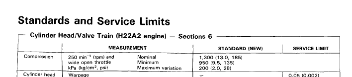
For those who don’t know what they’re looking at, the info states WOT and results to be in kPa (kg/cm2, psi). So it’s the second number in the brackets we’re interested. Low and behold the nominal compression psi for a new engine is 185psi nominal! I was shocked how bang on mine were!
It even gave a minimum result as low as 135psi. I would have got worried if I had at least 150-60psi personally.
The main thing for compression results is to have a consistency through all 4 cyclinders, again mine were bang on. So over the moon! The third figure is the maximum variation for service limits between cylinders = 28psi. Usually around 10% is rule of thumb.
So all well there. But as I like to write essays, here is a little cut and pasting to give people some more information on Compression testing and what things to look out for, what they mean and a further ‘wet’ test to confirm where pressure is being lost – downwards past the pistons/rings/cylinders or upwards through the head, usually a bad valve…
So there we go – engine appears healthy. A leak down test is another good test to find out the health of an engine, but couldn’t get the car to a tester. Looking at the above, I don’t see a great deal of point. I’m happy.
For those that have had 200psi, it may be the JDM H22A engines that run the extra 0.6 compression ratio that gains these results???
Seeing as though I’ll also be adding pressure to the combustion chamber in the form of boost from the supercharger the lower compression and lower compression test actually allows a little more scope for the high 9 psi I am planning. Like when people install pistons to raise compression down to like 8-9:0 compression to run high boosted turbo builds. Same principle, but on a smaller scope.
Now that I am happy to stick with my existing UKDM H22A2 for the build…let’s crack on with this…
Compression Test
Well, I’ve started a few things on the road to getting this project up to some speed. First thing to get out of the way, was to compression test my engine to see if I’m not wasting my time on a duff engine. I was expecting fairly ok results as it’s always made good power, fairly low mileage at 99k miles and has never missed a beat.
Borrowed a decent tester from a mechanic friend and ran the test as follows:
- Plug leads off
- Spark plugs all out
- Disconnect the dizzy electrical connectors
- (Optional – I didn’t bother) Pull fuel pump fuse/relay
- Screw in the tester to a cylinder
- Throttle pedal to the floor – wide open throttle (WOT)
- Crank it for around 10 seconds
- Take pressure reading
Repeat the above for each cylinder.
Here are the results:
1 -- 185psi
2 -- 185psi
3 -- 185psi
4 -- 185psi
At first I was disappointed as the readings seemed a little on the low side as I’ve read some H22A’s getting around 200psi a cylinder. So I checked the UK service manual and the UK H22A2 specs are as follows:
For those who don’t know what they’re looking at, the info states WOT and results to be in kPa (kg/cm2, psi). So it’s the second number in the brackets we’re interested. Low and behold the nominal compression psi for a new engine is 185psi nominal! I was shocked how bang on mine were!
It even gave a minimum result as low as 135psi. I would have got worried if I had at least 150-60psi personally.
The main thing for compression results is to have a consistency through all 4 cyclinders, again mine were bang on. So over the moon! The third figure is the maximum variation for service limits between cylinders = 28psi. Usually around 10% is rule of thumb.
So all well there. But as I like to write essays, here is a little cut and pasting to give people some more information on Compression testing and what things to look out for, what they mean and a further ‘wet’ test to confirm where pressure is being lost – downwards past the pistons/rings/cylinders or upwards through the head, usually a bad valve…
A compression test will tell you if your engine has good compression. An engine is essentially a self-powered air pump, so it needs good compression to run efficiently, cleanly and to start easily.
Low compression in one cylinder usually indicates a bad exhaust valve. Low compression in two adjacent cylinders typically means you have a bad head gasket. Low compression in all cylinders would tell you the rings and cylinders are worn and the engine needs to be overhauled.
If compression is low in one or more cylinders, you can isolate the problem to the valves or rings by squirting a little 30 weight motor oil into the cylinder through the spark plug hole and repeating the compression test. The oil temporarily seals the rings. If the readings are higher the second time around, it means the rings and/or cylinder is worn. No change in the compression readings tells you the cylinder has a bad valve.
So there we go – engine appears healthy. A leak down test is another good test to find out the health of an engine, but couldn’t get the car to a tester. Looking at the above, I don’t see a great deal of point. I’m happy.
For those that have had 200psi, it may be the JDM H22A engines that run the extra 0.6 compression ratio that gains these results???
Seeing as though I’ll also be adding pressure to the combustion chamber in the form of boost from the supercharger the lower compression and lower compression test actually allows a little more scope for the high 9 psi I am planning. Like when people install pistons to raise compression down to like 8-9:0 compression to run high boosted turbo builds. Same principle, but on a smaller scope.
Now that I am happy to stick with my existing UKDM H22A2 for the build…let’s crack on with this…
Last edited by nucleustylzlude on Thu May 26, 2011 9:37 pm, edited 2 times in total.
-
nucleustylzlude
- Moderator
- Posts: 4013
- Joined: Wed Aug 11, 2010 11:46 pm
- My Generation: 4G
- Location: Bristol, UK!
- Been thanked: 7 times
- Contact:
BUILD PART 5) - Build - Engine Parts Removals
PART 5) – BUILD!!!
Engine Parts Removals
Hey again everyone. Following my compression test and the lead up to Japfest, I spent a couple of hours in the garage working on my engine bay, removing various items and cleaning up the mess.
I managed to cover the following:
- Removal of more A/C piping
- Removal of EGR parts (mostly done)
- Removal of resonator bypass vacuum box, solenoid & bracket
- Removal of cruise control actuator
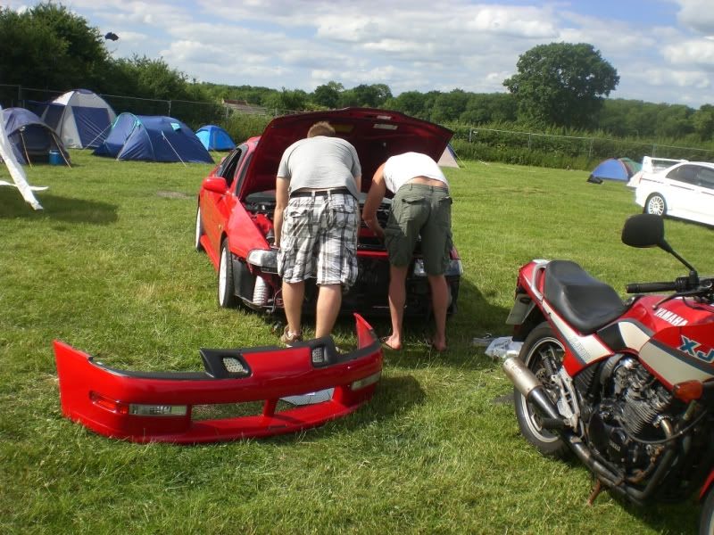
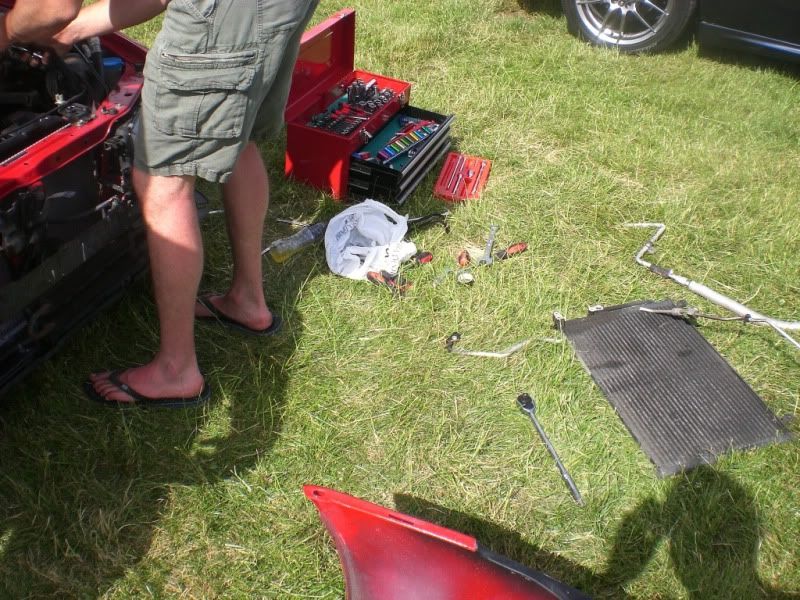
A/C system removal
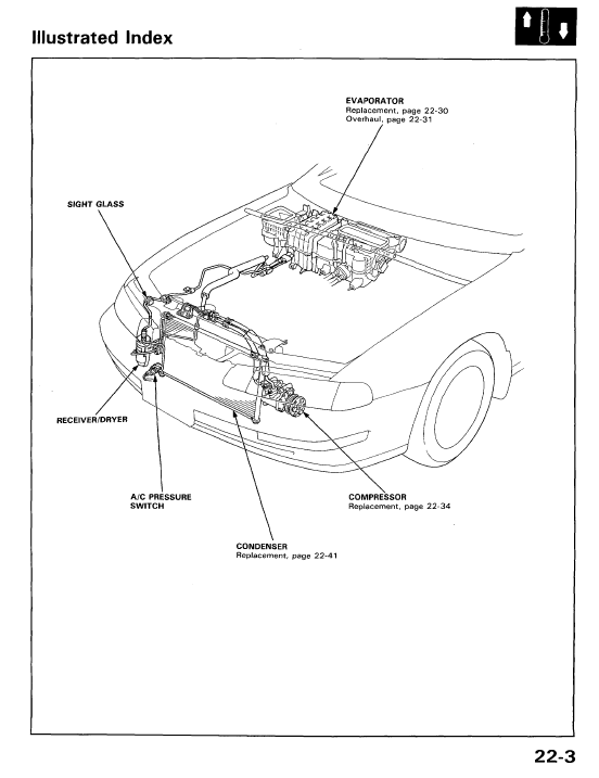
The A/C system already has most of the main parts stripped, which I did at Japshow last year with Jozefsan. So I’d already removed the A/C compressor, compressor brackets, some lines, condenser rad, receiver/dryer canister and some brackets. We disconnected the large pipe up to the large nut behind the passenger’s headlight. The smaller one was simply bent and snapped up to the edge of the condenser. The pipes are thin aluminium and bend and break easy if it helps you to remove them in parts.
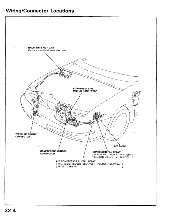
Here is a couple of snap shots of the A/C system from the service manuals, annoyingly shows the system for LHD cars. But apart from the lines routing to the passenger side, the main components are all the same.
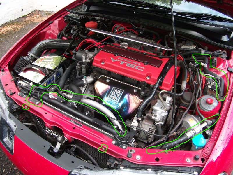
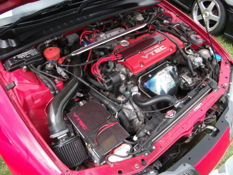
Here is a pic of my engine bay before Japshow, I’ve highlighted some of the visible parts:
When work began, check out the size of my @rse!

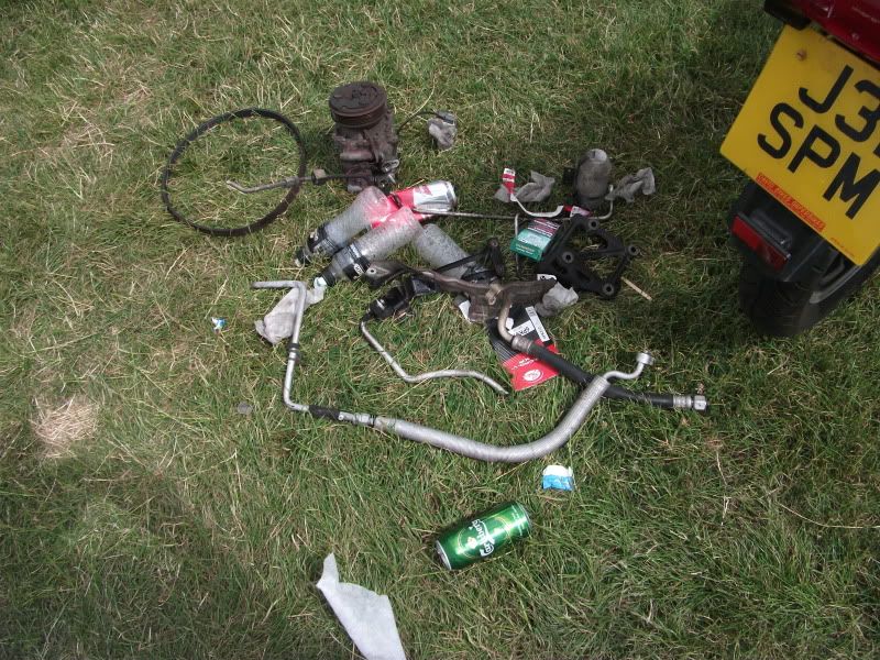
The fruits of our labour:
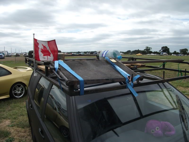
Condenser ended up on Crazy’s rat Ovlov:
And some shots of the compressor area and engine bay after:
Looks a little less busy – but lots more to go.
For anyone who wants to remove their aircon, you will need a shortened replacement belt to run just the alternator, part code 6PK913. Which means 6 ribs & 913mm long.
You will also need to remove the gas from the A/C system. I of course recommend it being done at a garage and properly degassed. But if you do just let the gas out, please do it outside in open air – it’s nasty stuff.
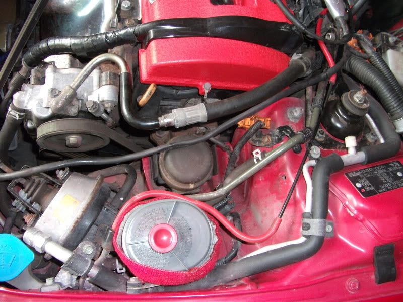
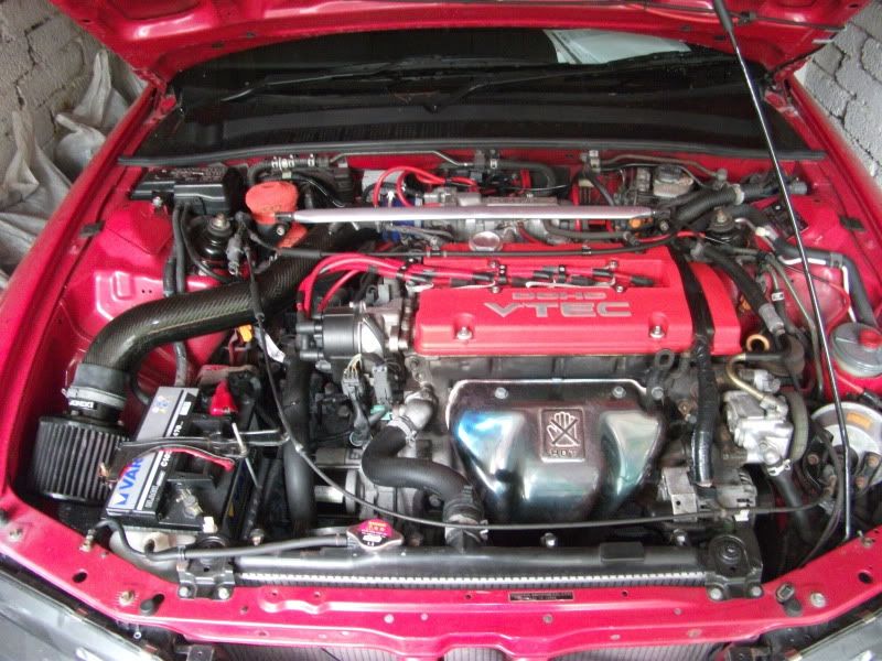
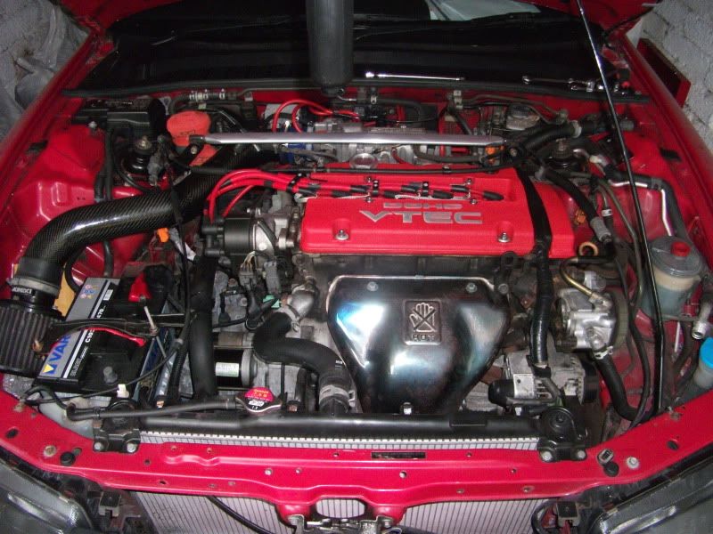
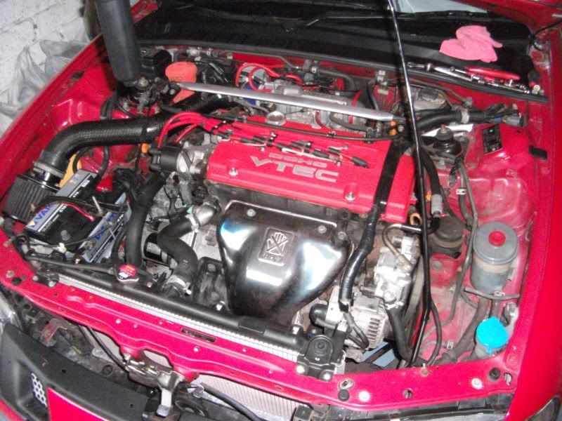
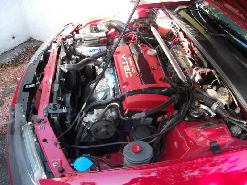
So, back to two weeks ago before Japfest. Here is how the engine bay was looking:
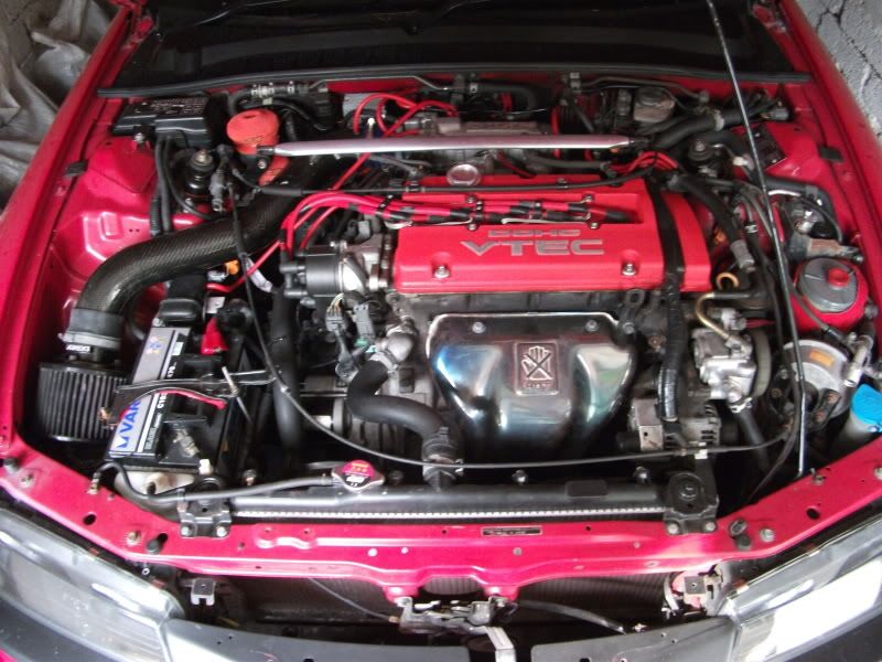
The plug cover was off being re-lacquered.
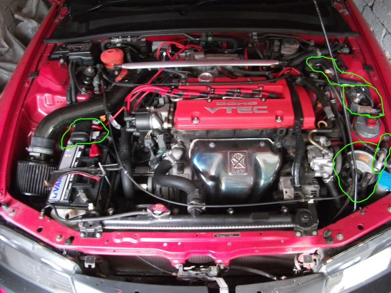
Here are the bits I am focusing on:
EGR parts Removal
Starting with the EGR parts first.
Just a quick note to say that the only reason I can remove my EGR valve and parts is because I already have my Hondata S300 running in the car on a tuned N/A map – where you won’t get a CEL code on the dash light like you will with a standard P13.
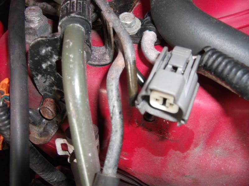
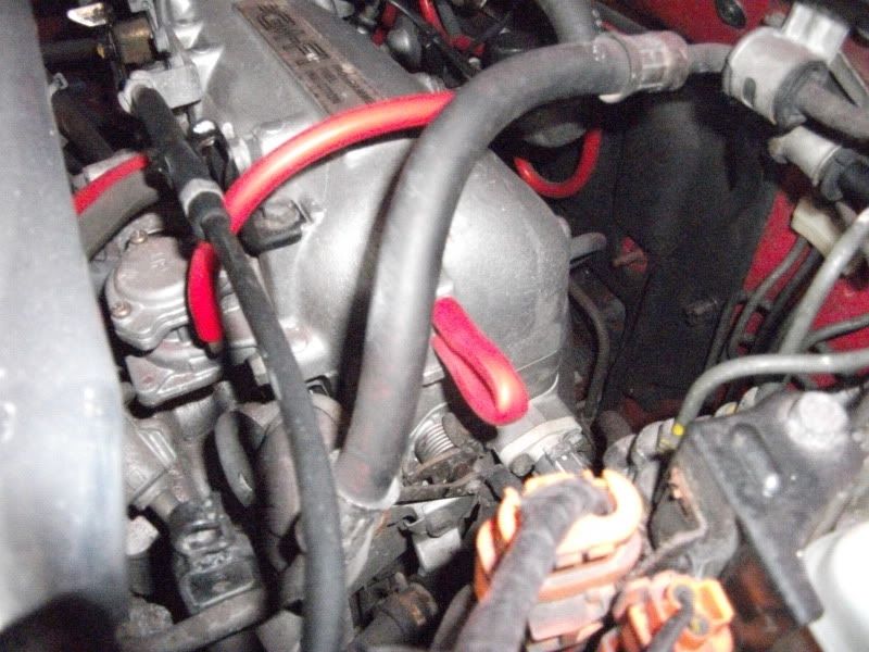
Here is the EGR valve on the drivers side top of the lower intake manifold:
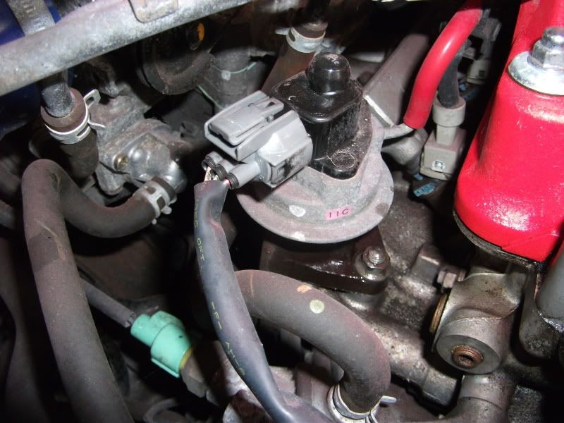
This has an electrical plug connected to it and a vacuum line that runs along the top of the injectors:
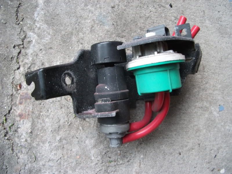
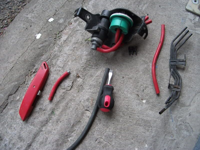
Then onto the EGR control solenoid valve & constant vacuum controller:
A vacuum line comes back through the same route and onto a vacuum port on the side of the intake manifold plenum.
I unclipped the electrical plug from the EGR control solenoid & constant vacuum, pulled the two vacuum lines from the hard lines on the strut tower. Two 10mm bolts later and voila!
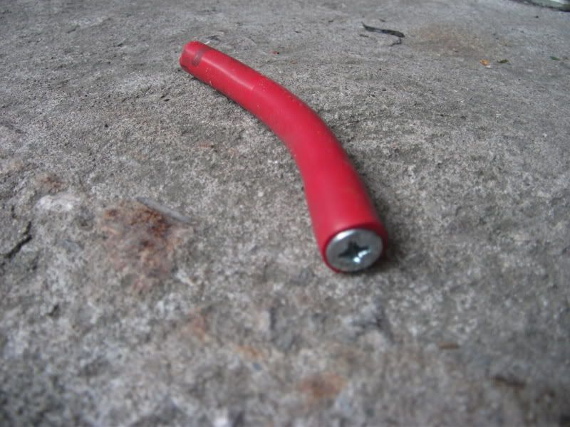
I removed the vacuum lines from the other side of the hard lines, the one going over the injectors to the EGR valve:
the other goes to the intake manifold – lower of the two:
Now that an intake port is exposed it needs to be plugged – I improvised with some of the removed Samco vac lines and a thick Ikea furniture bolt:
I also removed the hard lines from the shock tower. There is three lines here, two for the EGR and the third was for the cruise control – I temporarily made the line up from spare bits I’d removed as I hadn’t decided I was moving onto cruise control at this point:
Parts out so far:
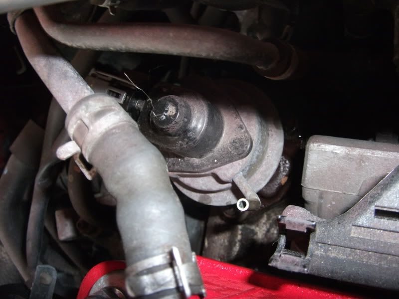
Final item to remove was to be the actual EGR valve on the intake manifold, I soaked the nuts in WD40 for quite a while and the few 1/4” drive 12mm sockets I had were 12 point and started to round the nuts off. They had to be 1/4” to enable a decent wobble socket to clear the Valve which slightly overhangs the nut. So I need to get a 1/4” drive 6 point socket to try before forking out for a rounded bolt/nut extractor set, or nut slitters.
So I’ll have to come back to the EGR valve.
Once it is out, you’ll be left with a big hole to fill on the lower intake manifold. I bought one of these aluminium blanking plates for the EGR a while ago from the states:
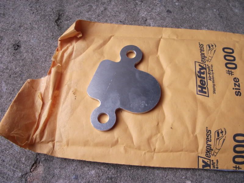
So I left the EGR in place but blanked the vacuum valve.
Onto the next item:
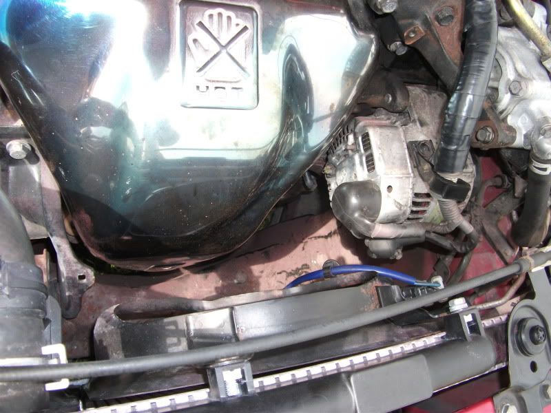
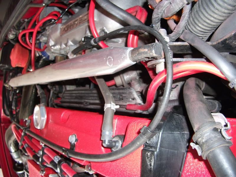
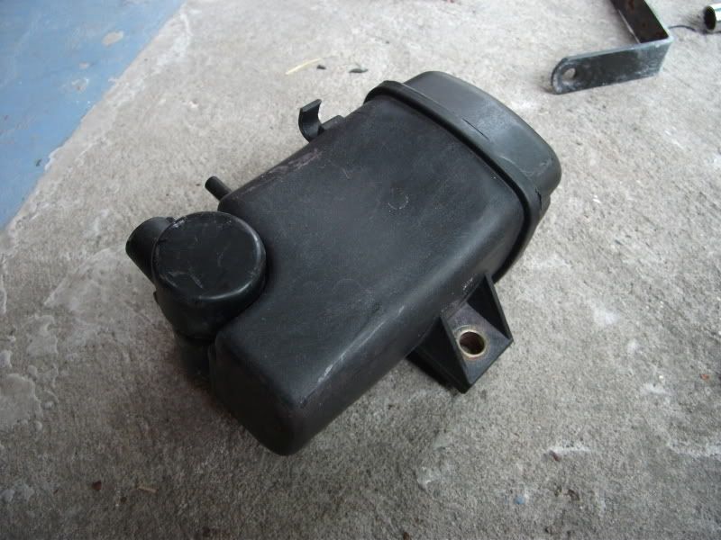
Intake resonator valve vacuum box and solenoid
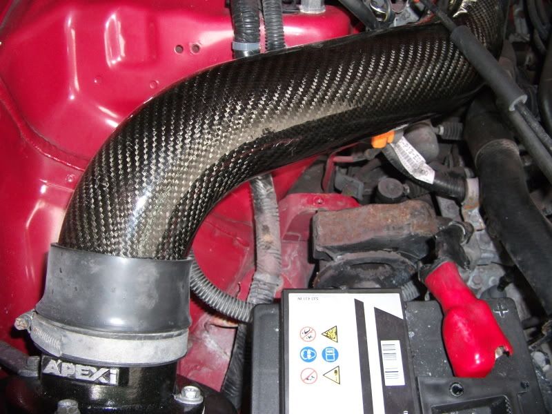
This is the item I am talking about, black box under the filter intake tubing. The solenoid is sat underneath the box too:
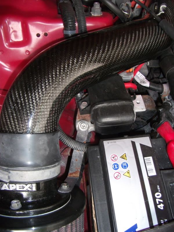
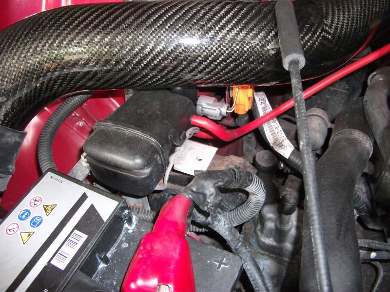
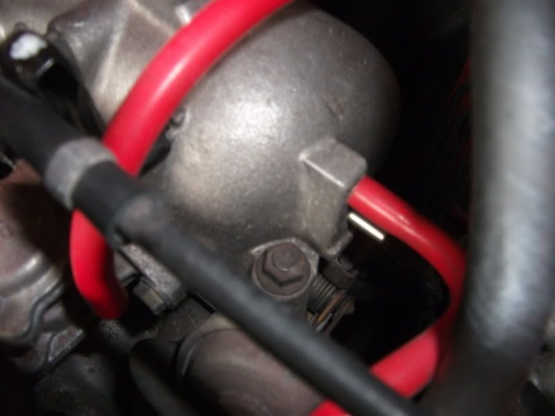
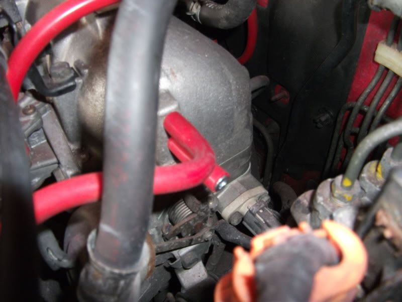
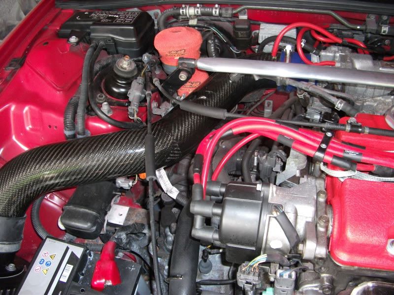
Easier to see on my engine bay, but the box/solenoid is connected to the intake manifold – it goes to the lower rear port on the top intake manifold plenum near the throttle body:
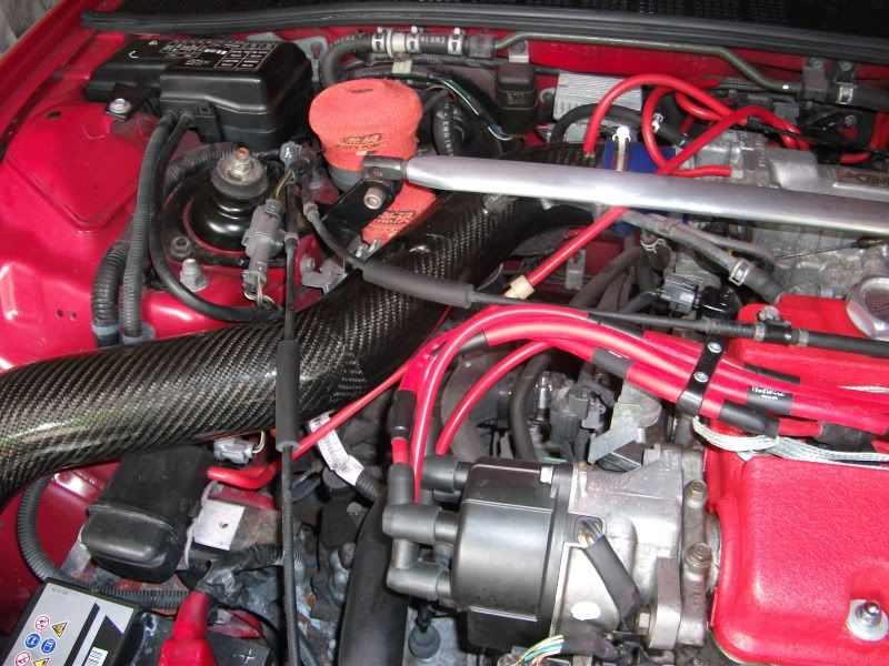
Normally routed around and under the intake tubing and has a one way valve half way along the vacuum line.
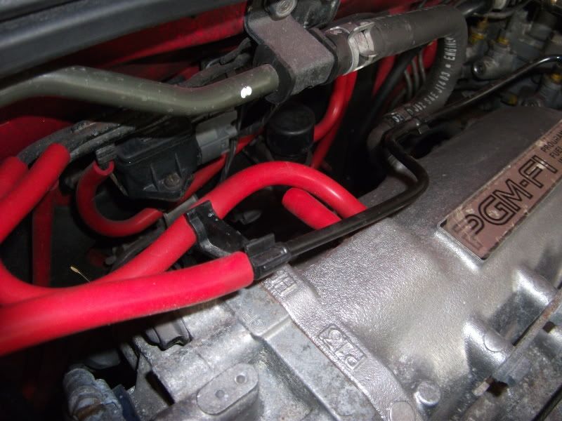
First things first, remove the vacuum line and block the port at the intake like I did before:
Then two 10mm bolts hold the vacuum box & solenoid onto a bracket that sits over the engine/gearbox mount. Remove:
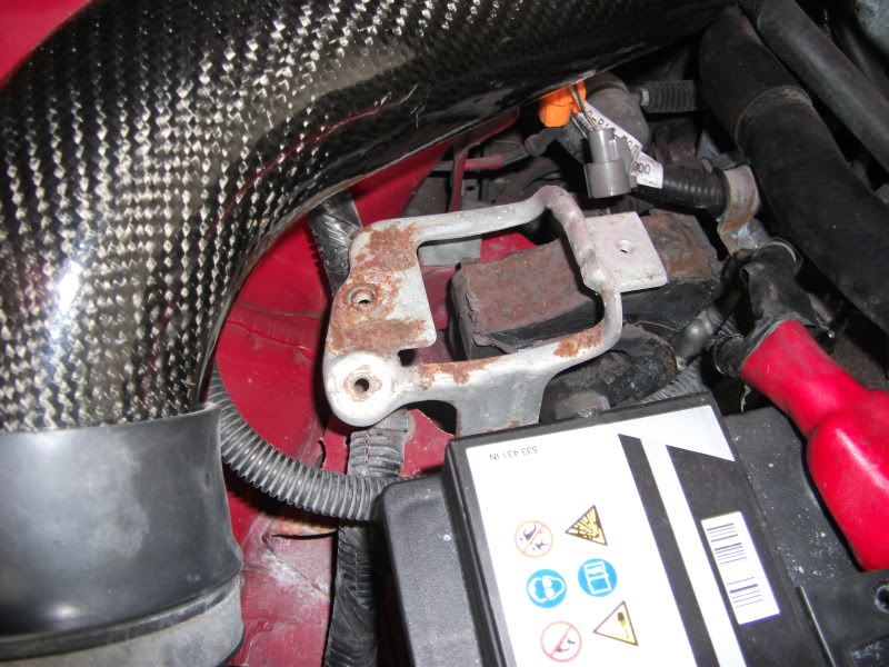
Another two 10mm bolts to remove the bracket:
That was as far as I got for that day.
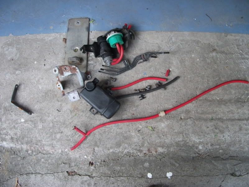
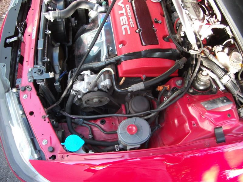
Here is everything removed and the finished results, still needs a good clean up though!
On to day 2, I moved onto the cruise control system and those pesky A/C line which seem to weave in and out of everything in the engine bay!
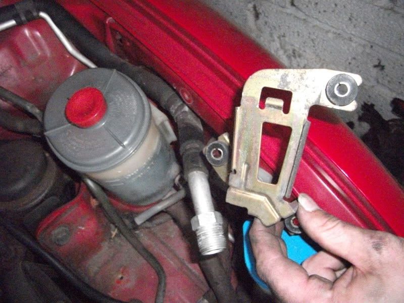
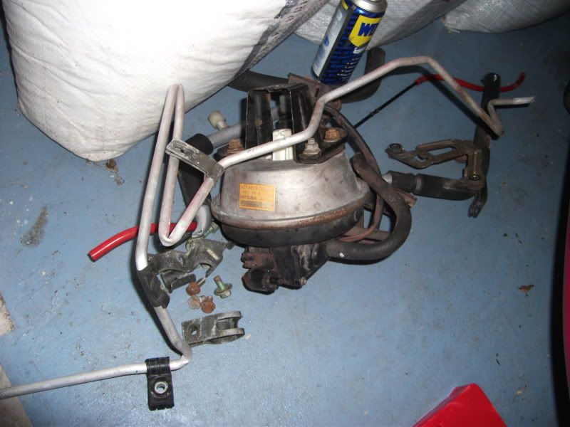
I took out the cruise control actuator first. I won’t lose it altogether as I want to retain the function on my Mugen steering wheel – I’ll be locating this somewhere out of the way – looking at behind the dash. I have to reroute the throttle cable / rewire the electrical connector / remove the vacuum box from behind the passenger wing and locate that with the actuator too.
No pics during removal, but you need to disconnect the throttle cable, remove the electrical connector and then remove the two 10mm bolts holding the cruise control bracket to the engine bay. Here is the end result:
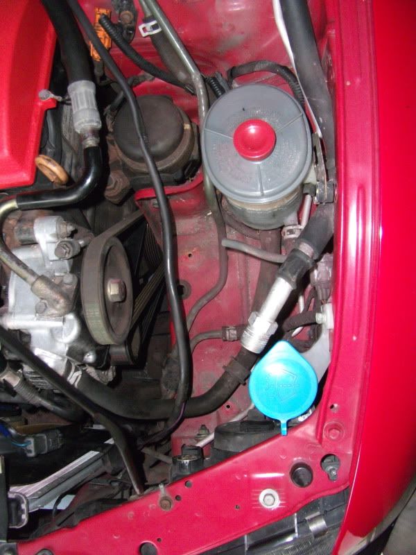
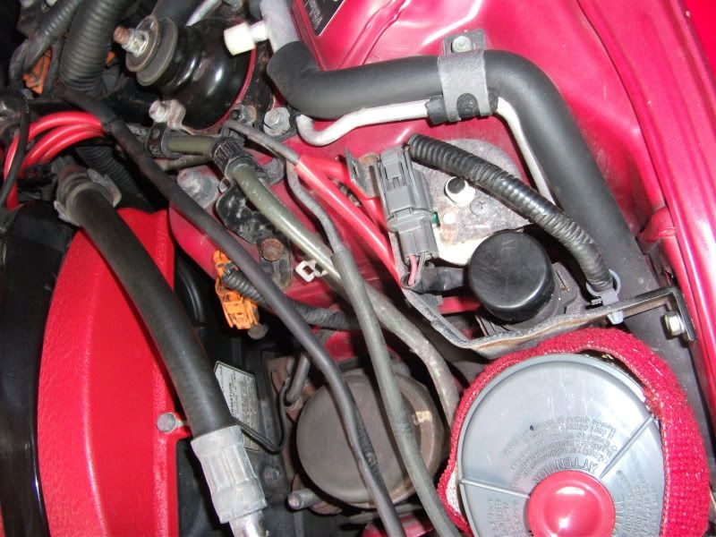
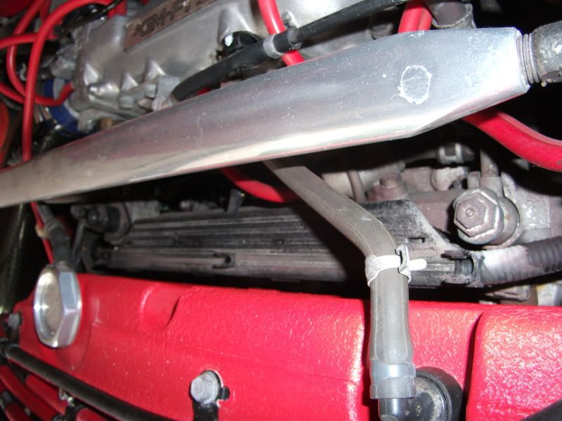
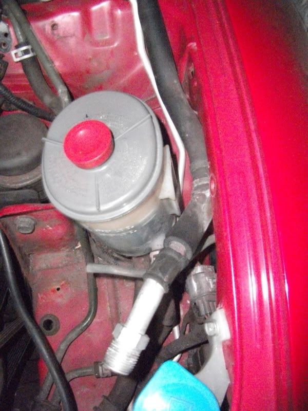
Then the A/C line goes around the back of the Power steering reservoir. The reservoir slides on out of it’s bracket, then force it to one side and under the three 10mm bolts holding on the bracket:
Now bar removing a couple of mounts to the A/C lines, all I had to do was manoeuvre them out. They are ok up to past the strut tower but then go down and under the ABS unit. So I bent and snapped them at this point. I’ll continue thee last part of the lines another time – I’ll have a quick look underneath but got a feeling it’s ABS out first – that’s for another day.
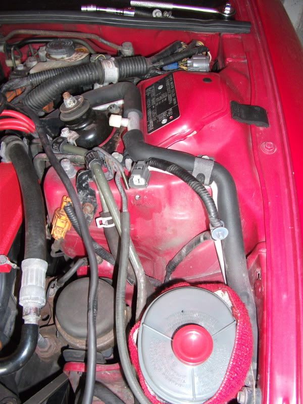
So the end result:
Parts removed:
Also the vacuum line that comes off the intake manifold to the cruise control was removed for now and instead of the bolt in some tubing, it was easier to loop the ports:
After a little clean before Japfest:

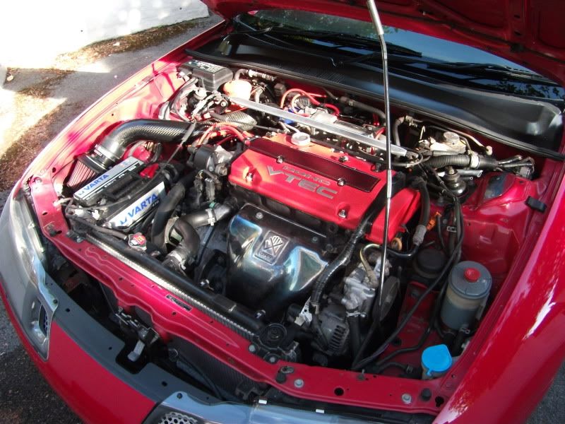
Lots better I’m sure you’ll agree.
Since Japfest, the A/C fan has gone too. I was gonna leave it and wire into my standard fan for extra cooling. But figured the less is more approach and 3 bolts later and it’s in the bin!
Next up will be the Power steering removal!
Cheers,
Rob
Engine Parts Removals
Hey again everyone. Following my compression test and the lead up to Japfest, I spent a couple of hours in the garage working on my engine bay, removing various items and cleaning up the mess.
I managed to cover the following:
- Removal of more A/C piping
- Removal of EGR parts (mostly done)
- Removal of resonator bypass vacuum box, solenoid & bracket
- Removal of cruise control actuator
A/C system removal
The A/C system already has most of the main parts stripped, which I did at Japshow last year with Jozefsan. So I’d already removed the A/C compressor, compressor brackets, some lines, condenser rad, receiver/dryer canister and some brackets. We disconnected the large pipe up to the large nut behind the passenger’s headlight. The smaller one was simply bent and snapped up to the edge of the condenser. The pipes are thin aluminium and bend and break easy if it helps you to remove them in parts.
Here is a couple of snap shots of the A/C system from the service manuals, annoyingly shows the system for LHD cars. But apart from the lines routing to the passenger side, the main components are all the same.
Here is a pic of my engine bay before Japshow, I’ve highlighted some of the visible parts:
When work began, check out the size of my @rse!
The fruits of our labour:
Condenser ended up on Crazy’s rat Ovlov:
And some shots of the compressor area and engine bay after:
Looks a little less busy – but lots more to go.
For anyone who wants to remove their aircon, you will need a shortened replacement belt to run just the alternator, part code 6PK913. Which means 6 ribs & 913mm long.
You will also need to remove the gas from the A/C system. I of course recommend it being done at a garage and properly degassed. But if you do just let the gas out, please do it outside in open air – it’s nasty stuff.
So, back to two weeks ago before Japfest. Here is how the engine bay was looking:
The plug cover was off being re-lacquered.
Here are the bits I am focusing on:
EGR parts Removal
Starting with the EGR parts first.
Just a quick note to say that the only reason I can remove my EGR valve and parts is because I already have my Hondata S300 running in the car on a tuned N/A map – where you won’t get a CEL code on the dash light like you will with a standard P13.
Here is the EGR valve on the drivers side top of the lower intake manifold:
This has an electrical plug connected to it and a vacuum line that runs along the top of the injectors:
Then onto the EGR control solenoid valve & constant vacuum controller:
A vacuum line comes back through the same route and onto a vacuum port on the side of the intake manifold plenum.
I unclipped the electrical plug from the EGR control solenoid & constant vacuum, pulled the two vacuum lines from the hard lines on the strut tower. Two 10mm bolts later and voila!
I removed the vacuum lines from the other side of the hard lines, the one going over the injectors to the EGR valve:
the other goes to the intake manifold – lower of the two:
Now that an intake port is exposed it needs to be plugged – I improvised with some of the removed Samco vac lines and a thick Ikea furniture bolt:
I also removed the hard lines from the shock tower. There is three lines here, two for the EGR and the third was for the cruise control – I temporarily made the line up from spare bits I’d removed as I hadn’t decided I was moving onto cruise control at this point:
Parts out so far:
Final item to remove was to be the actual EGR valve on the intake manifold, I soaked the nuts in WD40 for quite a while and the few 1/4” drive 12mm sockets I had were 12 point and started to round the nuts off. They had to be 1/4” to enable a decent wobble socket to clear the Valve which slightly overhangs the nut. So I need to get a 1/4” drive 6 point socket to try before forking out for a rounded bolt/nut extractor set, or nut slitters.
So I’ll have to come back to the EGR valve.
Once it is out, you’ll be left with a big hole to fill on the lower intake manifold. I bought one of these aluminium blanking plates for the EGR a while ago from the states:
So I left the EGR in place but blanked the vacuum valve.
Onto the next item:
Intake resonator valve vacuum box and solenoid
This is the item I am talking about, black box under the filter intake tubing. The solenoid is sat underneath the box too:
Easier to see on my engine bay, but the box/solenoid is connected to the intake manifold – it goes to the lower rear port on the top intake manifold plenum near the throttle body:
Normally routed around and under the intake tubing and has a one way valve half way along the vacuum line.
First things first, remove the vacuum line and block the port at the intake like I did before:
Then two 10mm bolts hold the vacuum box & solenoid onto a bracket that sits over the engine/gearbox mount. Remove:
Another two 10mm bolts to remove the bracket:
That was as far as I got for that day.
Here is everything removed and the finished results, still needs a good clean up though!
On to day 2, I moved onto the cruise control system and those pesky A/C line which seem to weave in and out of everything in the engine bay!
I took out the cruise control actuator first. I won’t lose it altogether as I want to retain the function on my Mugen steering wheel – I’ll be locating this somewhere out of the way – looking at behind the dash. I have to reroute the throttle cable / rewire the electrical connector / remove the vacuum box from behind the passenger wing and locate that with the actuator too.
No pics during removal, but you need to disconnect the throttle cable, remove the electrical connector and then remove the two 10mm bolts holding the cruise control bracket to the engine bay. Here is the end result:
Then the A/C line goes around the back of the Power steering reservoir. The reservoir slides on out of it’s bracket, then force it to one side and under the three 10mm bolts holding on the bracket:
Now bar removing a couple of mounts to the A/C lines, all I had to do was manoeuvre them out. They are ok up to past the strut tower but then go down and under the ABS unit. So I bent and snapped them at this point. I’ll continue thee last part of the lines another time – I’ll have a quick look underneath but got a feeling it’s ABS out first – that’s for another day.
So the end result:
Parts removed:
Also the vacuum line that comes off the intake manifold to the cruise control was removed for now and instead of the bolt in some tubing, it was easier to loop the ports:
After a little clean before Japfest:
Lots better I’m sure you’ll agree.
Since Japfest, the A/C fan has gone too. I was gonna leave it and wire into my standard fan for extra cooling. But figured the less is more approach and 3 bolts later and it’s in the bin!
Next up will be the Power steering removal!
Cheers,
Rob
So much to read. In heaven
Thought I'd put a note out re the engine mount inserts. Fitted a set the other day, made a massive difference to the feel of the car but she does vibrate a lot more However its not noticeable when actually moving, the biggest effect is when idling and starting up. However at certain RPM, even when cruising, door cards etc vibrate a small amount. Nothing that a bit of noise deadening won't sort (http://www.caraudiodirect.co.uk/second- ... allon.html) along with making sure all the screws are tight. My thinking goes that some of that deadning sludge will sort vibrations out.
See for where I got my idea So reduce the effects of the vibration and reduce road noise and improve audio, WIN/WIN/WIN!
Thought I'd put a note out re the engine mount inserts. Fitted a set the other day, made a massive difference to the feel of the car but she does vibrate a lot more
See for where I got my idea
Shiny wrote:I sniff dirty pants.
-
nucleustylzlude
- Moderator
- Posts: 4013
- Joined: Wed Aug 11, 2010 11:46 pm
- My Generation: 4G
- Location: Bristol, UK!
- Been thanked: 7 times
- Contact:
Re: Supercharged Mugen Lude
Hey bud.
Always lot's to read!
Thanks for the warning bud - but I don't drive it daily to care about things rattling - got weight saving in mind too, to add to the extra power. Hence all the engine part removals and recently stripped rear interior.
For what you need though, there's no denying that stuff /\ works well! Very impressive. All I could hear was how heavy it was though!
Will be removing all the factory sound deadening too, so no plan to add stuff back.
More to read, mini update...