Here's also some more info.
Stuff you will need
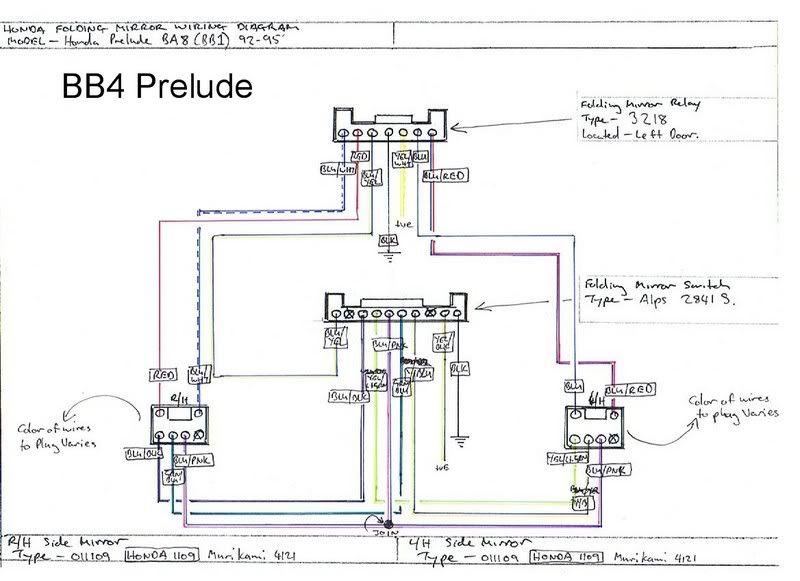
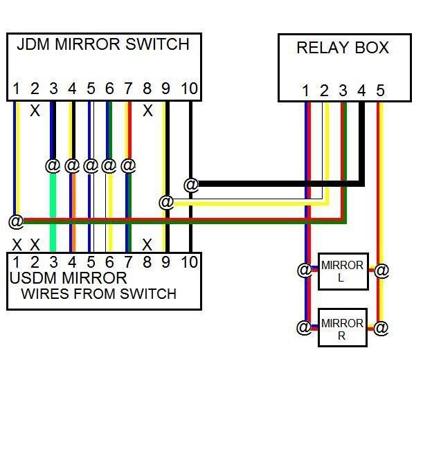
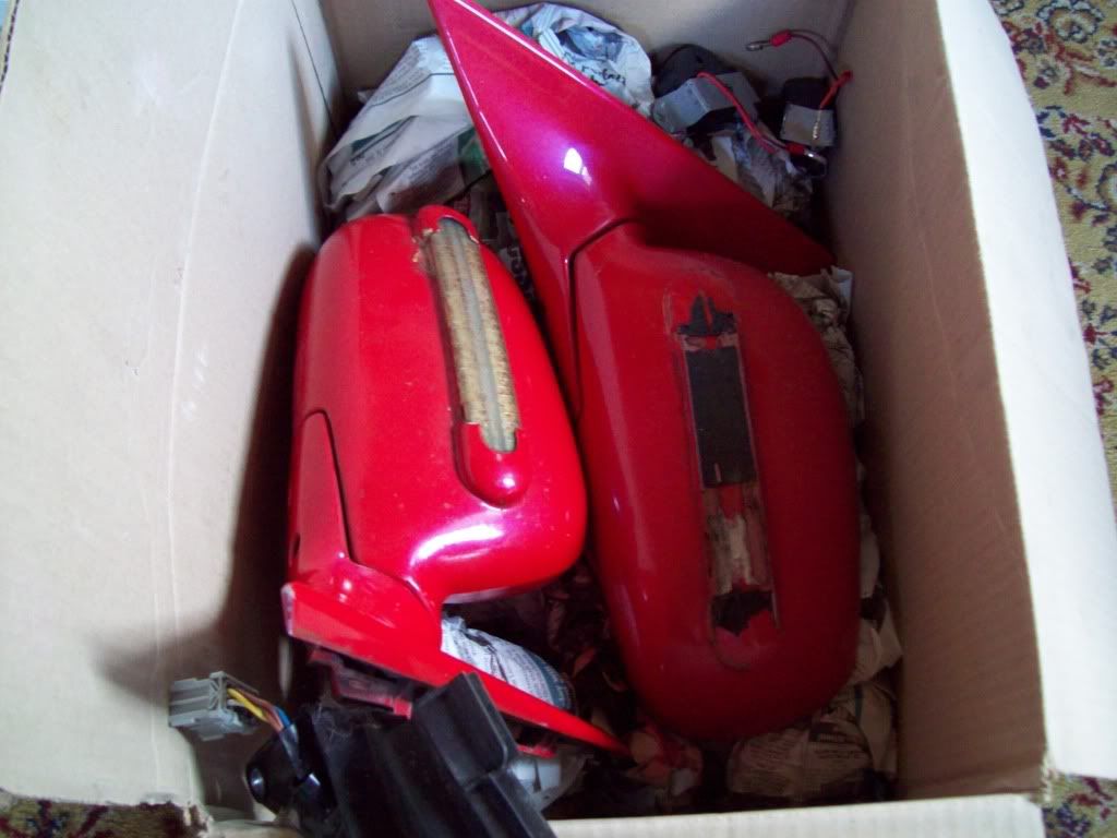
JDM power folding mirrors
and all the wiring i need
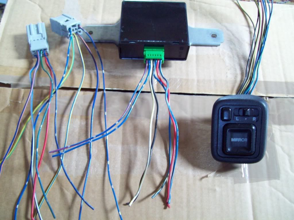
Relaybox
Powerfolding switch
Connectors for the wiring to the mirrors
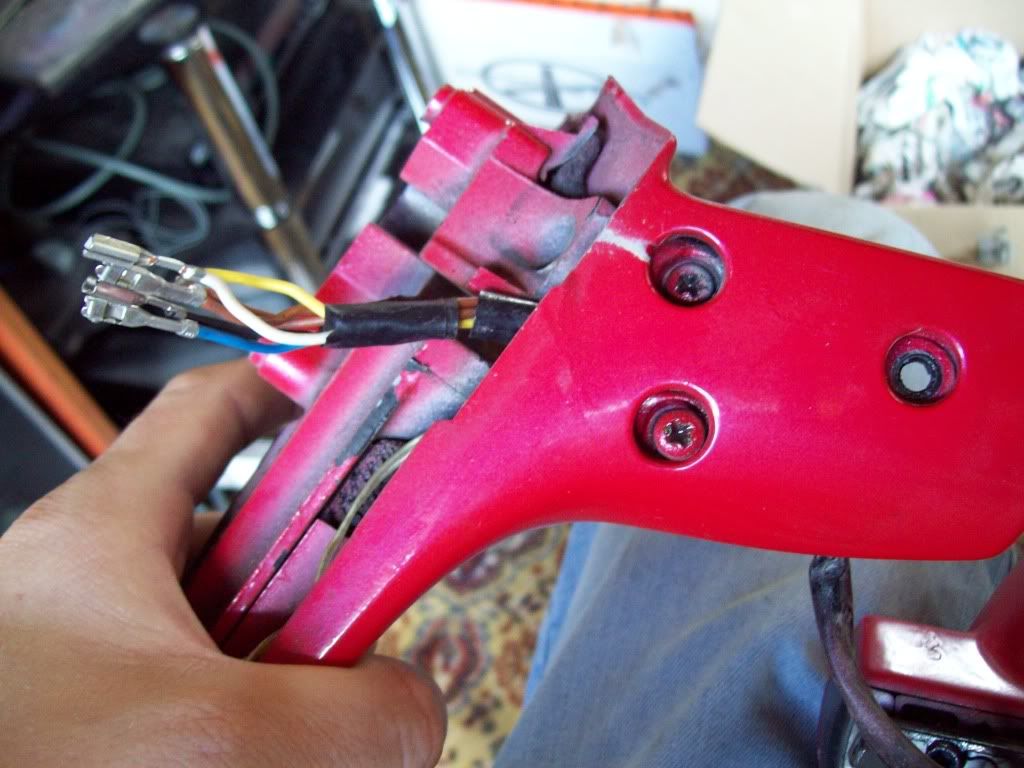
Used this writeup to dismatle the mirrors to get the folding mechanisms out as i'm still using my mirror housings
http://www.preludezone.com/showthread.php?t=745
(you need to register to view this)
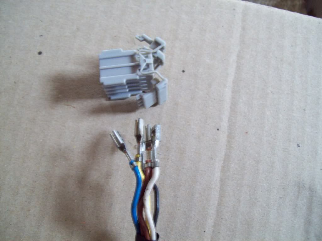
but the write-up didnt show you how the dismantle the connectors without cutting the wires so i thought i'd post a bit up
So on either side of the connector you have 2 little plates holding the wires in place
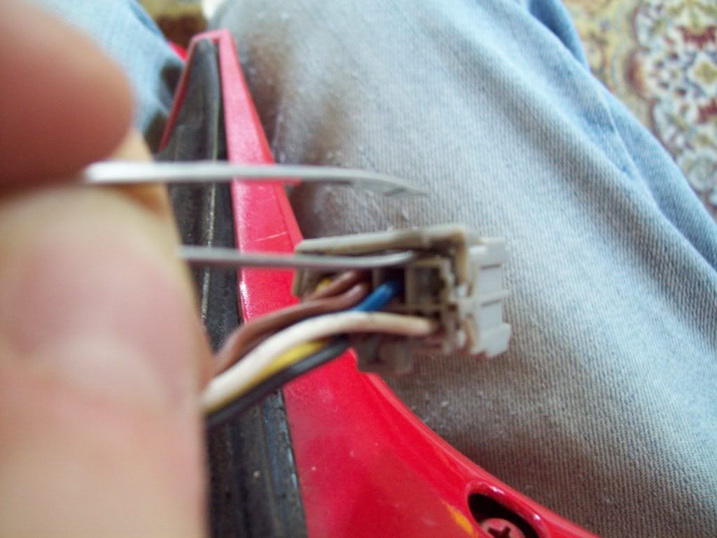
You need to get something like some tweezers or a flat headed screwdriver and gently ease it underneath the plates to pop them open like so
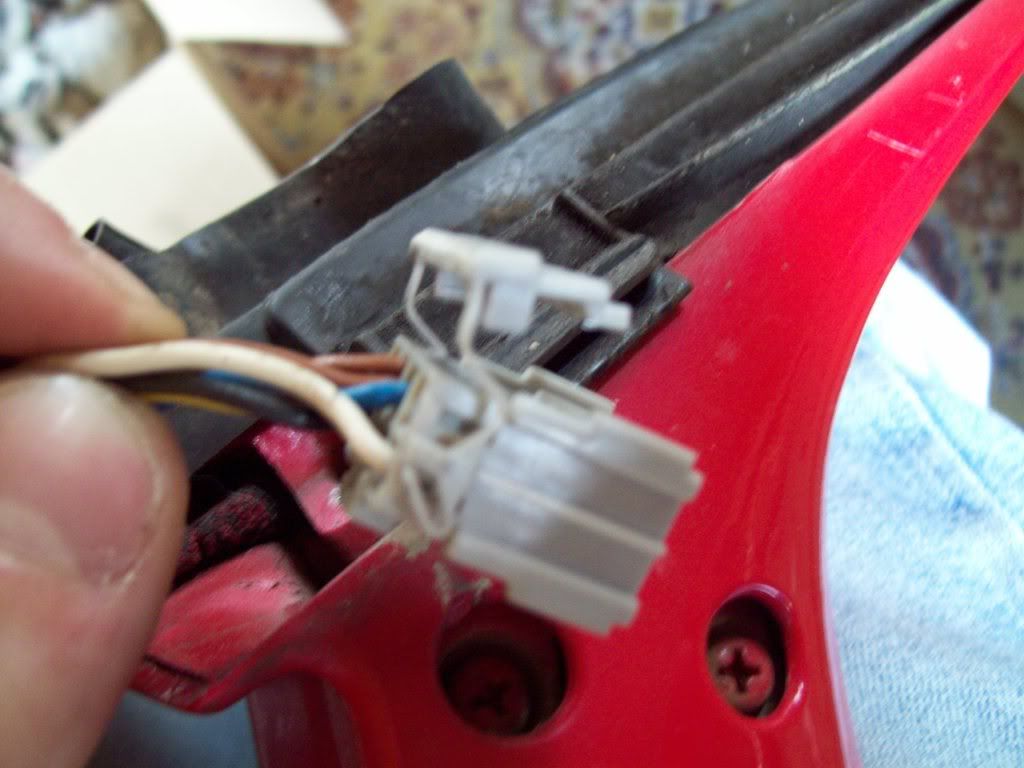
Once thats open you will have to get something like a needle or pin because also holding the wires in place are little clasps
Push the clasp back with the pin and the wire will just slide right out
(you will have to do this for each wire)
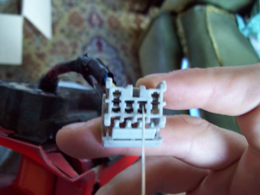
So now you have removed the connector without having to cut any of the wires
Thus allowing you to slide the wire through the mounting part of the mirror where the connnector is too big, so you dont have to cut and re-solder the wiring