Page 1 of 2
HELP - Rear fog light switch wiring
Posted: Sun Jun 08, 2014 1:10 pm
by gordonlear
I want to wire up a OEM rear fog light switch. My current not standard one only has 3 wires, earth, lights and fog lights.
The one I have from Honda has 5 wires as per picture below. Where do they all connect to?

Posted: Sun Jun 08, 2014 3:03 pm
by andypont
I have never been able to find a UKDM wiring diagram, but if nobody else can help in the next couple of hours I'll go out to my car with a meter and trace the wiring.
Posted: Sun Jun 08, 2014 5:10 pm
by andypont
Sorry I cant help. I put my meter across the pins and found that theres one pair connected all of the time but none appear to be connecting with the switch operation. Confused for a few minutes I kept checking different pairs before powering it up to actually try it and finding that my fog doesn't light up!

Anyone have a switch to sell me?
Posted: Sun Jun 08, 2014 7:53 pm
by gordonlear
Thanks for trying.
Posted: Wed Jun 11, 2014 9:50 pm
by gordonlear
Bump

Posted: Sun Jun 15, 2014 12:31 pm
by gordonlear
Someone must know the answer surely...........
Posted: Sun Jun 15, 2014 4:38 pm
by honda-hardy
I tried yesterday to find out what wires are what on mine, but all I kept on doing was blowing my sidelight fuse.
Posted: Sun Jun 22, 2014 8:17 pm
by gordonlear
Still looking for help on this one.
Posted: Sun Jun 22, 2014 9:56 pm
by andypont
Not sure this will be exactly what you need as I am a bit uncertain about the fog light circuit. I expected this to be a latching switch but it isn't. In other words the wires connected by operation of the switch are only connected whilst the switch is pressed. The signal must operate a latching relay that keeps the power on while required. However, I can tell you which pins are connected.
Assuming that Pin 1 is at the top (which is central to the switch body) - Red / Blue wire
Pin 2 - Black
Pin 3 - Red / Black
Pin 4 - Blue / White
Pin 5 - Red
Pins 1 & 2 and pins 3 & 5 make a circuit whilst the bulbs are in place. Pins 1 & 4 make a circuit whilst the switch is pressed.
Therefore (and I cant guarantee this so don't blame me if you blow fuses


) I believe that Pin 1 is the feed to the relay. Pin 2 is the earth from 'switch on' bulb, Pins 3 & 5 are the switch illumination (from your sidelight circuit) Pin 4 is the power from the ignition. I hope that's of some help
@gordonlear.
Posted: Sun Jun 22, 2014 10:09 pm
by wurlycorner
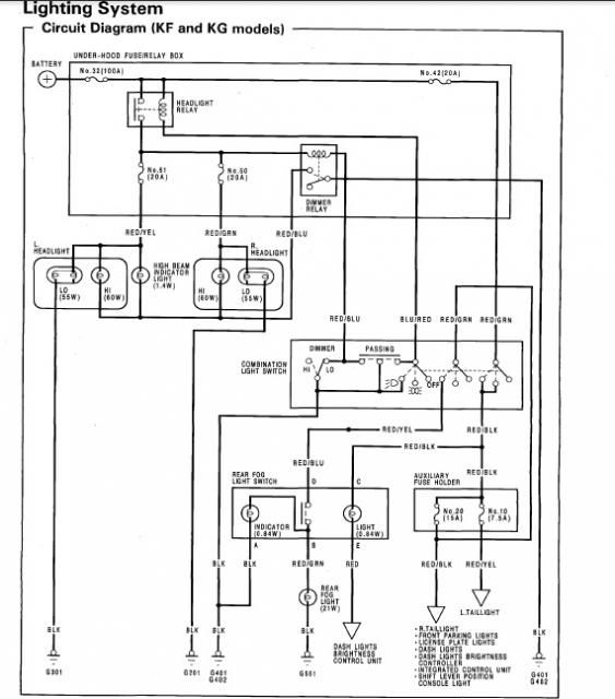
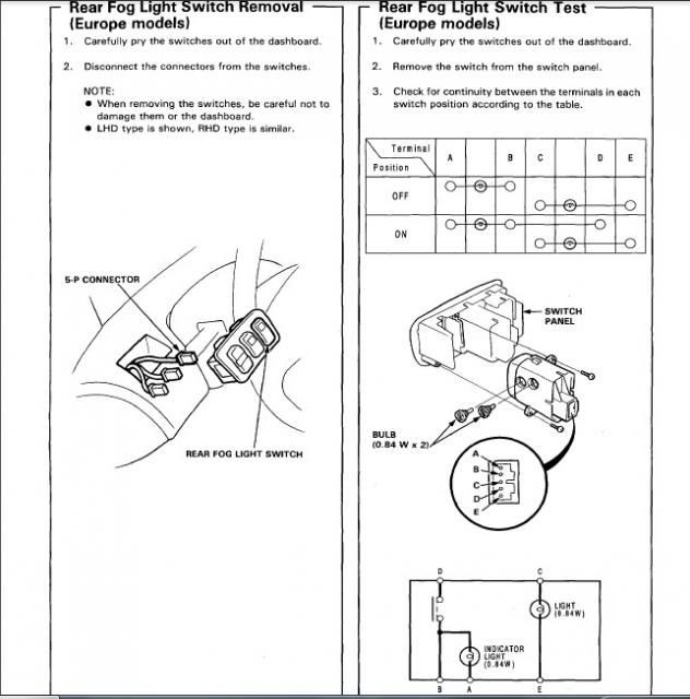
Page 23-237 of the 4th gen manual;
And page 23-232 of the same;