Page 1 of 11
Spoon P13 Chip Fitting Issues!
Posted: Tue Apr 02, 2013 8:18 pm
by CrunchyAdams82
Alright Chaps,
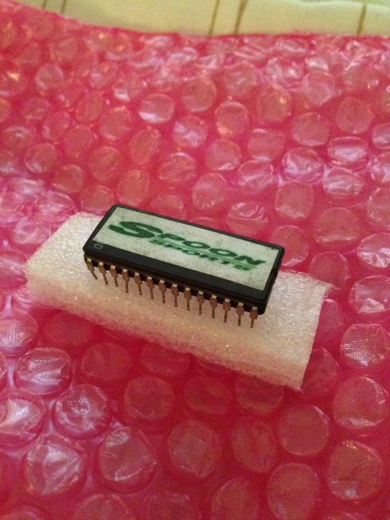
So, got my P13 Spoon Chip jobby through today from JDM-BB4, as described, but it looks like it's going to be a proper task to get it installed.
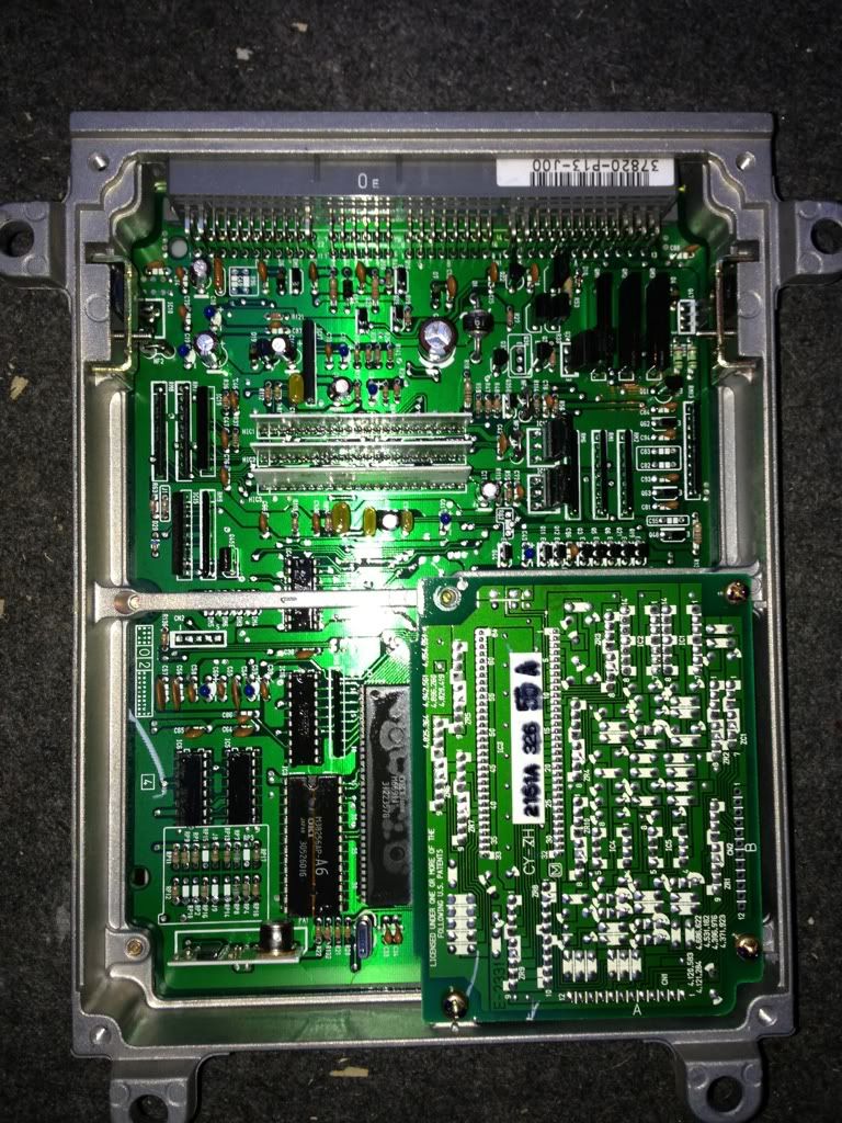
First things first, getting to the ECU..wow, that's a barrel of laughs isn't it?! But other than getting covered in sticky monk and almost breaking my thumb, I had a great time.

I'm having to use my existing ECU because it's a 4 pin rather than 3 (due to the traction control). This means I'm going to have to de-solder the OE chip & re-solder in the P13, rather than use a cradle.
Turns out this is going to be both tricky and risky, due to the precision required to pull the job off.

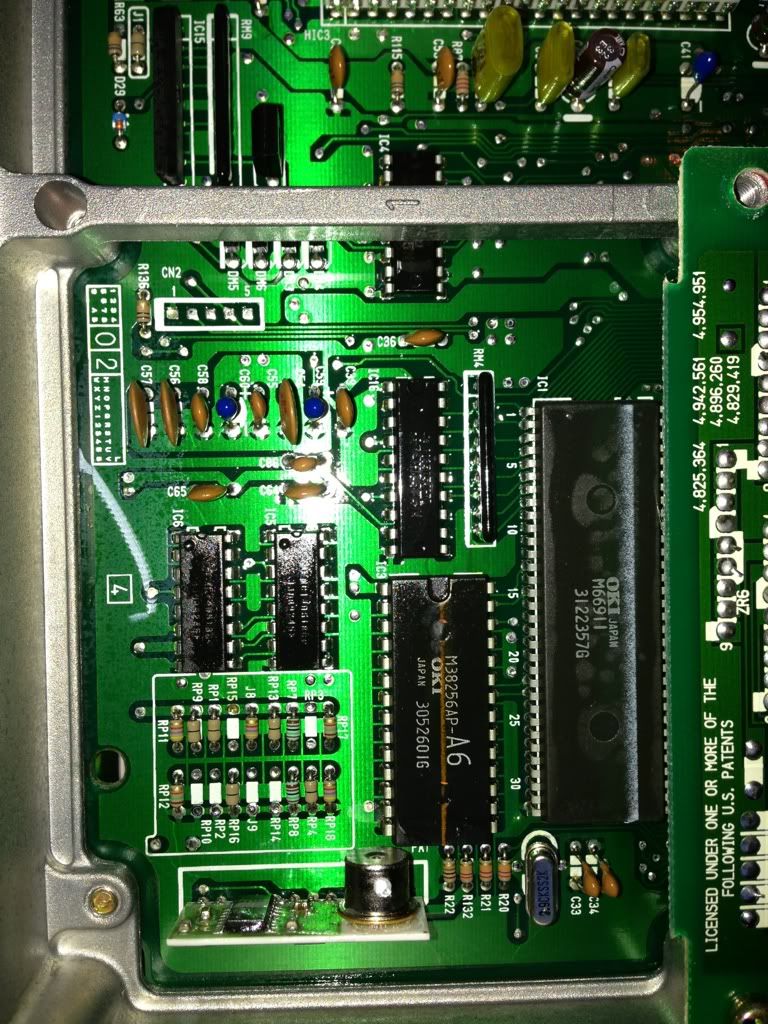
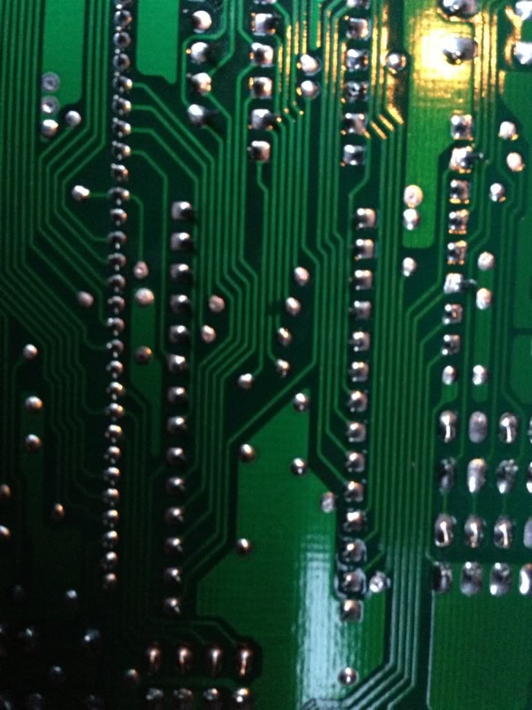
You've seen it all before, but here's what I'm dealing with;
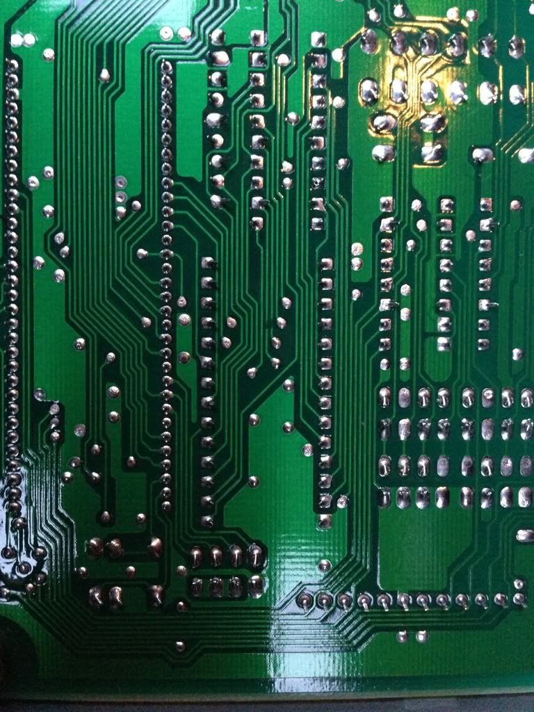
So as far as I can see, I don't have a great deal of options other than go for it, or leave it. I'm inclined to go for it I might add.
Just interested though if anybody has any suggestions that may make things easier? Or should I take it to an electrician of sorts, who would no doubt have all the correct tools & find this exceptionally simple?
Any ideas appreciated.
Thanks.
Posted: Tue Apr 02, 2013 8:24 pm
by chrismc
If you have the option then I'd get a socket & get that fitted by a TV/Electronics expert initially.
Removes the risk of frying your new chip during soldering..
You can then just simply fit the chip afterwards with no risk
Posted: Tue Apr 02, 2013 8:27 pm
by CrunchyAdams82
Yeah, that's a good shout actually.

Where can I find the socket/cradle that I need?
Posted: Tue Apr 02, 2013 8:32 pm
by Dbo
or contact bluejackhustler on here

he was going to do a deal with rob
as in rob sells the chips he fits them

he is expert at it as they are soldered both sides of the motherboard

you really need skills to do this and it really needs a socket

cant stress that enough

the bloke who did mine said it was one of the toughest he had ever tried and no margin for error
Posted: Tue Apr 02, 2013 8:46 pm
by CrunchyAdams82
Hmm, ok. Does sound like I need to get a socket & get things done professionally then.
I'll take it into work tomorrow & have a better look at it under a microscope. I build fibre optic lasers for a living, and use a soldering iron on a daily basis. I'm just not sure if the iron tips we use are fine enough for the work that needs doing.

I'll check it out though & re-post with the outcome.

Posted: Tue Apr 02, 2013 8:48 pm
by littlefeller
if you dont use an iron every day then leave well alone, its very easy to lift a pad or two with something this delicate. if you must then use side cutters to remove the original chip then desolder the leads, just utube this option to see what im saying. i once came across a board even more delicate than this, im no expert but i can solder quite well, i was doubtful but then had a cool idea, i simply cut the leads with side cutters and soldered the socket via extra thin wire straight to the now cut but still soldered and attached leads, then set the whole lot in resin, worked a treat. if in doubt dont do this rechip
Posted: Tue Apr 02, 2013 8:59 pm
by CrunchyAdams82
You know what littlefeller, all those ideas had crossed my mind, apart from the resin. Good thinking.

The only problem with this technique is if I drokk it up, there's no easy way of re-using the original chip. But that really would make things a hell of a lot easier!
What kind of resin did you use, & to what end?
Lastly, the chip can be fitted the correct way, or upside down of course.. How do I know I'm getting it right? Do I just use my common sense? It seems pretty obvious tbh - the writing is the same way up front & back. Shall I just install it the same way up as the existing chip?
Posted: Tue Apr 02, 2013 9:12 pm
by littlefeller
the chip (as all chips) have a half moon kinda shape at one end, this is the guide for almost all chips, the moon pattern will prob be printed on the board underneath the chip, take a closer look at the chip and your see what im talking about. why not practice on old electrical boards before hand. i resined the leads/wires and chip, this was to prevent any shorts, you could use any type of resin that doest conduct, i used the resin found in fibreglass but silicone would also work just as well, aybe better as it could be removed if you wished. why not try this tecnique on something else (cut out chip then reattach chip either direct - ie lead to lead or safest bet with wires then test the item, if it works it would give you more confidence) no confidence will kill your ecu as you will be nervouse and fook up. practice first with something not so important
Posted: Tue Apr 02, 2013 9:25 pm
by Ammo
I did mine recently, and made a bit of a mess
Until I bought one of these
http://www.ebay.co.uk/itm/Aluminium-Sol ... 3cce600f39
Heat each solder point up till it melts, use the sucker, move onto the next one, and repeat till the chip freely comes out.
Just be VERY careful and take your time, you don't want to break any tracks on the ECU board
I'd advise soldering in a Socket rather than the chip direct into the ECU for a couple of reasons
1. You can always change back to the old chip with ease if needed
2. Sockets are cheap and if you balls one up soldering it in it's not the end of the world
Posted: Tue Apr 02, 2013 9:27 pm
by CrunchyAdams82
Excellent advice, thankyou.
I assume by the 'half moon' shape, you are referring to the 1mm cutout on one end? That makes a lot of sense now & looks pretty foolproof. (famous last words)!
Yeah, it would be a good idea to do some practice first, but I don't really have anything to hand to test on. I'm pretty confident with a soldering iron anyway, & fundamentally, I'll sit down studying it at work tomorrow for a good 10-15 mins, & will ultimately only attempt it if I believe after that time that it's within my capabilities.
So we'll see what happens tomorrow I guess..
Regarding resin, I've got access to a variety of types - including silicone. So I may well utilise that as described, if successful.
Thanks for your help, I appreciate it.