Congratulations to vtecmec for winning May/June's Lude Of The Month, with his DIY Turbo BB1 build.

>>> Click Here For Profile <<<

Image

DSP wiring: 3 unknown wires

To clarify - that's In Car Entertainment - not frozen water
User avatar
Froidas
Posts: 253
Joined: Mon Jan 30, 2012 11:11 am
My Generation: 4G
Has thanked: 4 times
Been thanked: 1 time

DSP wiring: 3 unknown wires

Post by Froidas » Thu Aug 08, 2013 7:57 am

I have EDM Prelude and full DSP system, but can't use it because of 3 unkown wires. It is a couple years old problem. Tried to search, even had a chance to examine another Prelude with DSP (will explain later). But no luck. I really hope somebody can help me.

So, my DSP system consists of:
* wiring harness
* double din player
* front centre speaker
* rear centre speaker with amplifier
* CD changer

Symptoms: I connected everything. Double din turns on, plays CD, but volume is super quite. It is impossible to tell the words of the song, etc. So I guess amplifier is not working. So I start checking everything and found this (below).

Problem: my Prelude EDM audio connector (No. 1 in the scheme) has 3 empty places, where DSP connector (No. 2 in the scheme) has 3 wires:
* green/blue
* green/white
* green/black

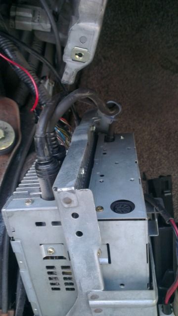
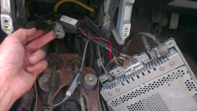
Some pictures to get the idea.

DSP wiring harness scheme:
Image

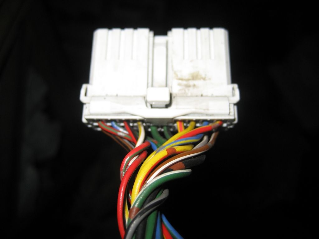
Prelude EDM audio connector (No. 1 from the scheme):
Image

Please note 3 empty wire holes.
Image

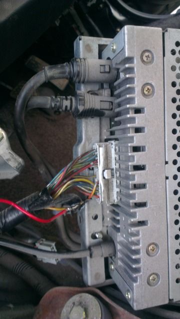
DSP harness connectors (No. 2 and 3):
Image

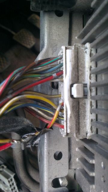
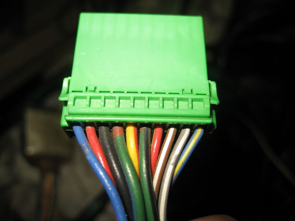
DSP harness audio IN connector (No. 2):
Image

Please note 3 green/xxx wires. No. 1 connector has 3 empty holes here.
Image

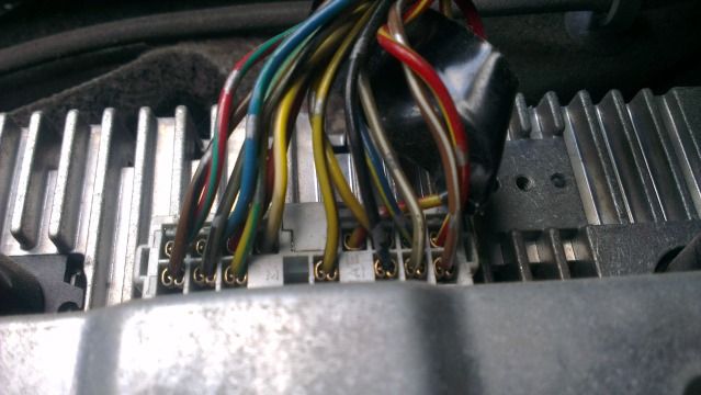
DSP harness audio unit connector (No. 3):
Image
Image

DSP amplifier connector (No. 4):
Green/black and green/blue goes here too.
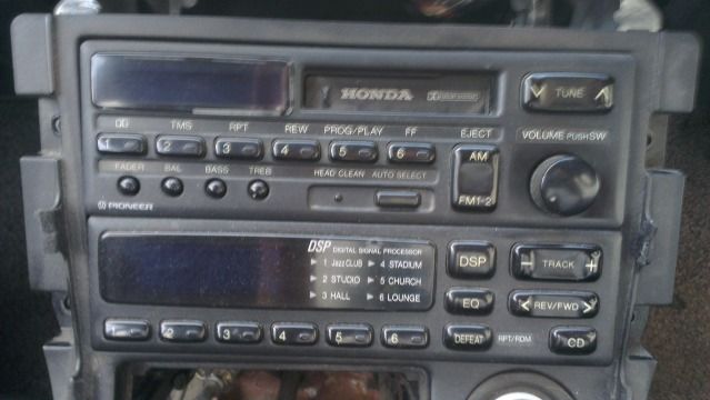
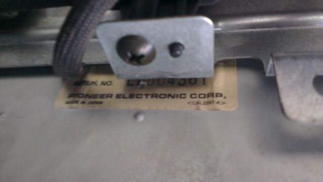
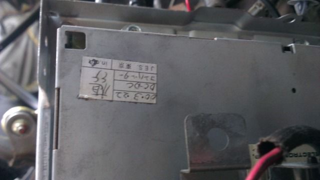
Image

Image

Audio unit model:
Image

-------------------------------- Part 2 --------------------------------

My friend examined another JDM Prelude with DSP system. Turns out, it looks the same, but is different. Audio unit code is different, it has no separate wire harness, so in this case there's only one connector, going to audio unit (only No. 1 instead of No1, 2 and 3 from the scheme). And instead of 3 green/xxx wires, it has 2 yellow/xxx wires.

Image

Image


Conclusion: I guess green/blue (or yellow/green) is constant positive and green/black (yellow black) is ground. But what about green/white ? It might be "one turn of the ignition key". But I wont try connect any positives until I am sure. I will ask my friend to check those 2 yellow with a tester and update this thread. Any ideas are appreciated.

P.S. I tried to write everything as clear as possible. If something is not clear to you, just ask.
Yellow Dream made true.

User avatar
wurlycorner
Ye are glad to be dead, RIGHT?
Posts: 21217
Joined: Sat May 19, 2012 3:33 pm
My Generation: 4G
Location: Chelmsford, Essex
Has thanked: 1958 times
Been thanked: 239 times

Post by wurlycorner » Thu Aug 08, 2013 11:40 am

I have a JDM with original OEM full DSP setup, but I've never had it apart or looked round the system tbh so unfortunately I can't speak with authority here and am just commenting from 'basic principles', if you like.

It might well be an ignition live is missing and it isn't turning on the amp?

Car amps normally have a main power live and 'remote' signal. The main power live is what it actually uses for juice, remote is the signal that tells the amp to turn on.
In basic terms... Without the amp being on, the head unit is effectively pushing sound into the amp but there'll be nothing coming out, because the transistors will be in their off state (not letting current flow).
That being the case though, if you can hear anything, I'm surprised. :?

User avatar
Froidas
Posts: 253
Joined: Mon Jan 30, 2012 11:11 am
My Generation: 4G
Has thanked: 4 times
Been thanked: 1 time

Post by Froidas » Thu Aug 08, 2013 12:13 pm

Thanks for input. I will connect everything again and try to play. But, if I imagine correctly, that on/off wire should come from the audio unit ? In my case all 3 green wires should come from under the dash.

Would you have time to take out double din player and check the big connectors behind him? If it would have 3 green/xxx wires, I would ask you to check them with tester.
To avoid unnecessary disassembling, here's what I noticed:
* my DSP units (with 3 green wires) have "Gathers" markings and model names on both units onthe lower left corner:
* my friends DSP units (with 2 yellow wires) have "Honda" markings and no model names on the front. All buttons and design are identical to my ones.

My units:
Image
Yellow Dream made true.

Danzley0
Posts: 248
Joined: Sun Jun 09, 2013 8:43 pm
My Generation: 5G
XBOX GamerTag: Danzley0

Post by Danzley0 » Thu Aug 08, 2013 5:31 pm

Normally means someone messed around with speaker wires in the past but that looks too clean for that to have happened sometimes there is a 2nd fuse box with a fuse gone try that?

User avatar
wurlycorner
Ye are glad to be dead, RIGHT?
Posts: 21217
Joined: Sat May 19, 2012 3:33 pm
My Generation: 4G
Location: Chelmsford, Essex
Has thanked: 1958 times
Been thanked: 239 times

Post by wurlycorner » Fri Aug 09, 2013 9:45 am

Those are the same 2 units that I have in mine.

I'll try and have a look over the weekend for you.

Never taken this stereo out before though, how do you get it out exactly?

User avatar
Froidas
Posts: 253
Joined: Mon Jan 30, 2012 11:11 am
My Generation: 4G
Has thanked: 4 times
Been thanked: 1 time

Post by Froidas » Fri Aug 09, 2013 10:31 am

Yes ! Big expectations for 3 green wires :)

1. Remove the big plastic audio and gear stick surrounding
2. Either remove the hole unit as in the picture above, or remove cassette/radio player part separately.
Yellow Dream made true.

User avatar
wurlycorner
Ye are glad to be dead, RIGHT?
Posts: 21217
Joined: Sat May 19, 2012 3:33 pm
My Generation: 4G
Location: Chelmsford, Essex
Has thanked: 1958 times
Been thanked: 239 times

Post by wurlycorner » Fri Aug 09, 2013 10:48 am

:?
I was hoping you wouldn't say that...
You do realise if I tackle this job now, it leaves me with no excuses for not getting on with fitting the new front speakers (wiring the crossovers directly back to the H/U), new gear-gaitor and new carpet? And the carpet means sorting the accelerator pedal and ECU?
:cry:

:evil:

:bat:
:troll:

User avatar
Froidas
Posts: 253
Joined: Mon Jan 30, 2012 11:11 am
My Generation: 4G
Has thanked: 4 times
Been thanked: 1 time

Post by Froidas » Fri Aug 09, 2013 4:27 pm

Actually, no :) Look this way: only several bolts and thats it, 10 minutes and you can check the wires, another 10 and everything is assembled as it was :) It's far bigger job to change carper, or speakers :)

By the way, brand new OEM Honda carpet or good condition used one?
Yellow Dream made true.

User avatar
wurlycorner
Ye are glad to be dead, RIGHT?
Posts: 21217
Joined: Sat May 19, 2012 3:33 pm
My Generation: 4G
Location: Chelmsford, Essex
Has thanked: 1958 times
Been thanked: 239 times

Post by wurlycorner » Fri Aug 09, 2013 4:53 pm

Good used - funds wouldn't stretch further than that!

I know what you mean, but if the centre console has come out, I might as well change the carpet, 'because that's the most faffy bit about changing it really and then the rest snowballs from there... :(

User avatar
wurlycorner
Ye are glad to be dead, RIGHT?
Posts: 21217
Joined: Sat May 19, 2012 3:33 pm
My Generation: 4G
Location: Chelmsford, Essex
Has thanked: 1958 times
Been thanked: 239 times

Post by wurlycorner » Mon Aug 19, 2013 7:37 pm

@froidas

Ok, I've had it out this evening - thanks for the reminder, otherwise I'd have missed the opportune moment!

So it seems I have the same model as your friends? (it has Honda branding on the front). It also only has 1 loom plug.

Image

I haven't had it out of the cage so you haven't got the full part number. I'll do it if you need to see it, but otherwise I'd rather leave as is?
Image
Image

General view of the rear connections. The empty DIN socket is where the lead to the autochanger goes (it's unplugged) and it has 2 other cables that are hard wired out of the back of the DSP unit with DIN plugs on the end, that are plugged into the head unit. I guess one is sound out of the headunit (pre-amp) into the DSP, then the other is DSP adjusted pre-amp sound back in to headunit so it can be passed through the headunit amps and into the speakers?
Image
Cable in my hand is the autochanger lead. The silver box plugged into the aerial lead and with a red cable spliced into the main loom is the frequency exchanger I expect.
Image

Image

Close up of one side of the connector.
Image

Close up of the other side of the connector.
Image
Last edited by wurlycorner on Mon Aug 19, 2013 9:45 pm, edited 1 time in total.

Post Reply

Return to “Electrical / Lights / ICE”