Congratulations to vtecmec for winning May/June's Lude Of The Month, with his DIY Turbo BB1 build.

>>> Click Here For Profile <<<

Image

Tach wire feed from instrument cluster

To clarify - that's In Car Entertainment - not frozen water
Post Reply
User avatar
106pete
Posts: 1139
Joined: Wed Dec 01, 2010 9:38 am
My Generation: 4G
Location: Cornwall
Been thanked: 1 time

Tach wire feed from instrument cluster

Post by 106pete » Thu Aug 01, 2013 10:54 am

I don't know why I'm finding this so hard but I need the signal wire for the rev counter please if anyone can help.

This is the plug I'm aiming for
Image
236bhp and 170ft/lb stock :whistle:

User avatar
Merlin
Moderator
Posts: 12393
Joined: Fri Aug 06, 2010 9:04 am
My Generation: 5G
PSN GamerTag: Merlinbadman
Location: Edinburgh
Has thanked: 68 times
Been thanked: 303 times

Post by Merlin » Thu Aug 01, 2013 11:06 am

Have you removed the clocks from the dash?
Image
BA8......... BB4......... BB8.........The JDM Muscle Bus

User avatar
106pete
Posts: 1139
Joined: Wed Dec 01, 2010 9:38 am
My Generation: 4G
Location: Cornwall
Been thanked: 1 time

Post by 106pete » Thu Aug 01, 2013 11:28 am

Yeah it's all out mate
236bhp and 170ft/lb stock :whistle:

User avatar
Merlin
Moderator
Posts: 12393
Joined: Fri Aug 06, 2010 9:04 am
My Generation: 5G
PSN GamerTag: Merlinbadman
Location: Edinburgh
Has thanked: 68 times
Been thanked: 303 times

Post by Merlin » Thu Aug 01, 2013 11:30 am

And you cant see the wire you want on the plug for the speedo cluster?
Image
BA8......... BB4......... BB8.........The JDM Muscle Bus

User avatar
106pete
Posts: 1139
Joined: Wed Dec 01, 2010 9:38 am
My Generation: 4G
Location: Cornwall
Been thanked: 1 time

Post by 106pete » Thu Aug 01, 2013 11:36 am

Yeah there's 3 wires for the current rev counter and I don't know which one is the signal feed?
236bhp and 170ft/lb stock :whistle:

User avatar
Merlin
Moderator
Posts: 12393
Joined: Fri Aug 06, 2010 9:04 am
My Generation: 5G
PSN GamerTag: Merlinbadman
Location: Edinburgh
Has thanked: 68 times
Been thanked: 303 times

Post by Merlin » Thu Aug 01, 2013 11:36 am

The service manual says the wire to the igniter unit should be blue. Although do we even have igniter units? I am not familiar with dizzy's :? or the difference to US ones.

4th gen service manual RHD gauge diagram from page 23-146:

Image

Image
Image
BA8......... BB4......... BB8.........The JDM Muscle Bus

User avatar
Merlin
Moderator
Posts: 12393
Joined: Fri Aug 06, 2010 9:04 am
My Generation: 5G
PSN GamerTag: Merlinbadman
Location: Edinburgh
Has thanked: 68 times
Been thanked: 303 times

Post by Merlin » Thu Aug 01, 2013 12:33 pm

See on the above diagram, the tachometer igniter unit wire. It has B3 next to it. Does that mean is from pin 3 on connector B? If so that is on the drivers side of the speedo cluster (the opposite side to which I think you are looking at).
Image
BA8......... BB4......... BB8.........The JDM Muscle Bus

User avatar
106pete
Posts: 1139
Joined: Wed Dec 01, 2010 9:38 am
My Generation: 4G
Location: Cornwall
Been thanked: 1 time

Post by 106pete » Thu Aug 01, 2013 12:44 pm

Hmm yeah I am looking at the passenger side connector and when it's disconnected the rev counter dies so I assumed it was that one.

I'll check out that b3 wire soon as I get home from the mot on my polo.

Cheers pete
236bhp and 170ft/lb stock :whistle:

User avatar
Merlin
Moderator
Posts: 12393
Joined: Fri Aug 06, 2010 9:04 am
My Generation: 5G
PSN GamerTag: Merlinbadman
Location: Edinburgh
Has thanked: 68 times
Been thanked: 303 times

Post by Merlin » Thu Aug 01, 2013 12:57 pm

@106pete before you go looking at the other side I have made a mistake and got confused with the wiring diagrams :facepalm: 
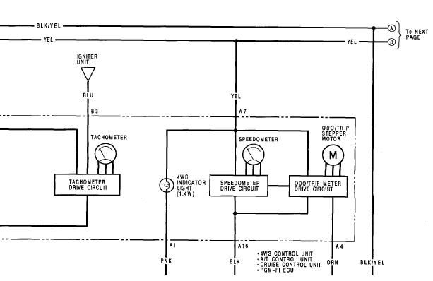
. The one above is the LHD one from page 23-149.

On the RHD wiring diagram from page 23-153 it says that wire is A1 which would mean you are looking at the right connector (the double row one). Which would make more sense.

Image

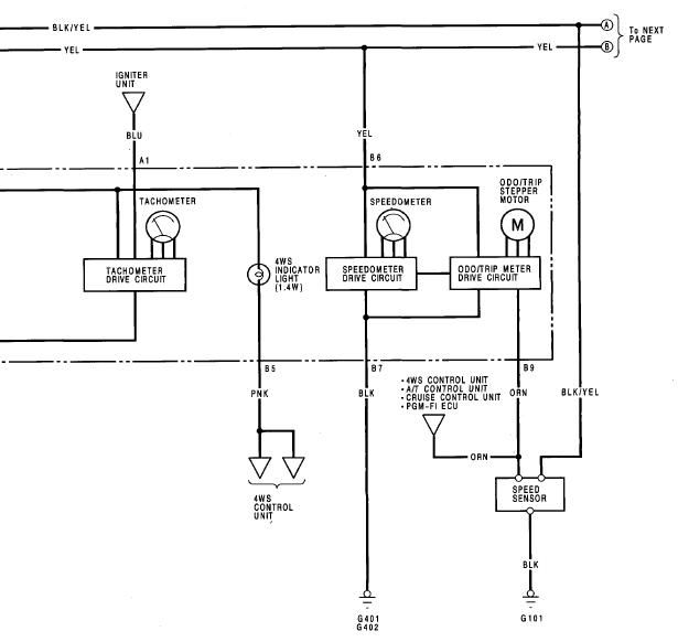
The wiring diagrams give these as the wires (which nicely matches your pic of the connector):

A1 - (Blue) 
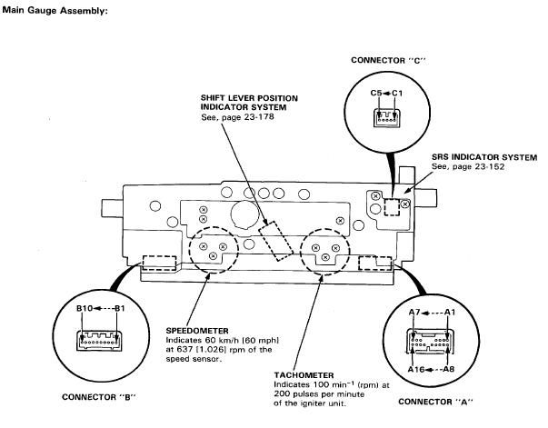
Tachometer Igniter unit
A2 - (Black) Gorund
A3 - (Red/Yellow) High beam indicator light
A4 - (Red/Blue) High beam dimmer relay
A5 - (Green/Blue) Left turn signal indicator light

So going by the diagrams A1 should be the wire in the bottom right of your picture:

Image
Image
BA8......... BB4......... BB8.........The JDM Muscle Bus

User avatar
106pete
Posts: 1139
Joined: Wed Dec 01, 2010 9:38 am
My Generation: 4G
Location: Cornwall
Been thanked: 1 time

Post by 106pete » Thu Aug 01, 2013 5:52 pm

Thanks merlin that's perfect

For the min as I was rushing I've connected it to the blue wire by the drive side strut but I don't know if its related, now my cel light is flashing up after a few mins of driving.

Really big problem because I don't have my diagnostic port anymore, it was...lost during a big wire clean up lol
I better start looking at where the wires should come from to replace it.

For now as a guess I have removed the egr valve to replace with a clean one once its cooled.
236bhp and 170ft/lb stock :whistle:

Post Reply

Return to “Electrical / Lights / ICE”