Congratulations to vtecmec for winning May/June's Lude Of The Month, with his DIY Turbo BB1 build.
>>> Click Here For Profile <<<

>>> Click Here For Profile <<<
Confused's Long-Term Anglia Project
-
honda-hardy
- Club Cartographer
- Posts: 6268
- Joined: Sat Jan 28, 2012 7:35 pm
- My Generation: 5G
- Location: chippenham
- Been thanked: 1 time


-
nucleustylzlude

- Moderator
- Posts: 4013
- Joined: Wed Aug 11, 2010 11:46 pm
- My Generation: 4G
- Location: Bristol, UK!
- Been thanked: 7 times
- Contact:
Great work as usual Gary!
Love that fuel tank - been meaning to speak to them about a catch tank. How much was that out of interest?
And nice choice on the chargecooler - the barrel designs are very efficient, PWR make some of the best ones around in that design but cost an arm and a leg!
Loving all the work so far, its great to see a father and son project like this. Nice to know there are some good Dads out there.
-
Confused

- Posts: 749
- Joined: Fri Jan 27, 2012 11:44 am
- My Generation: 4G
- Location: Notts / Essex
- Has thanked: 3 times
- Been thanked: 11 times
- Contact:
You gotta speed it up, and then you gotta slow it down
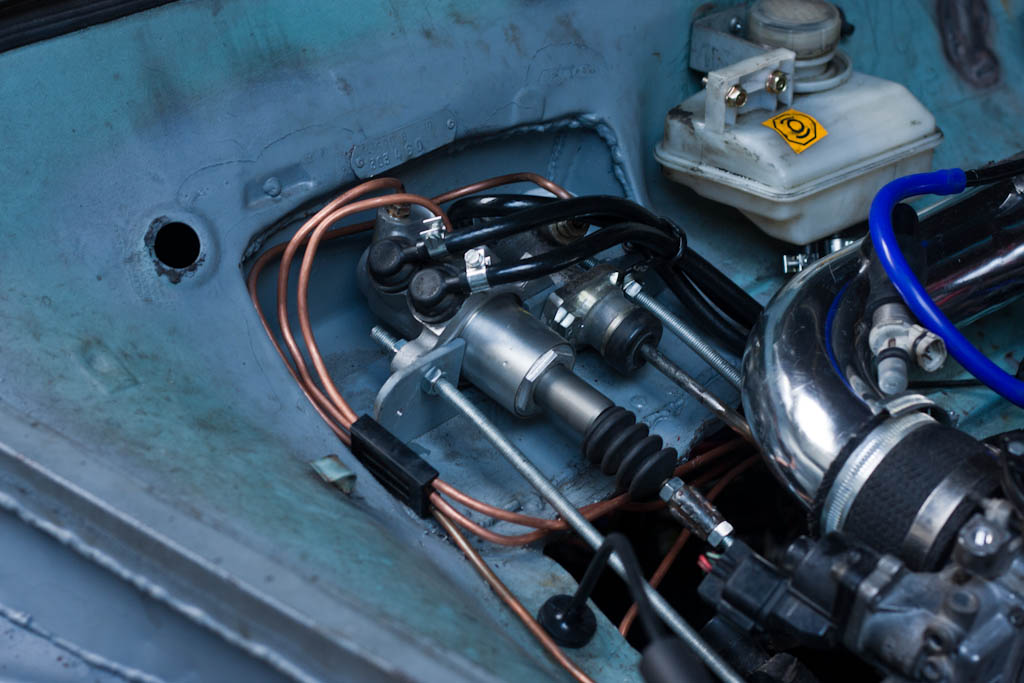
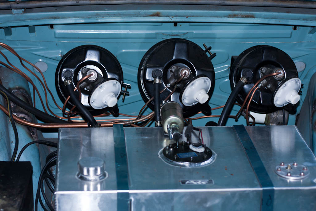
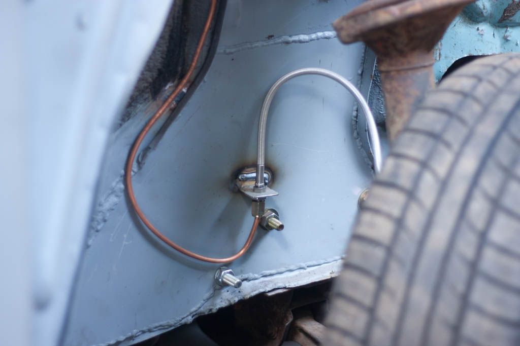
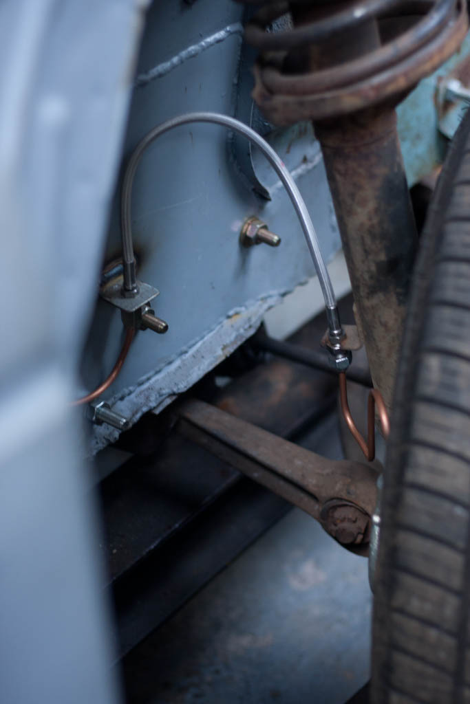
I began last time to fit the brakes to the car, and the most of the work on the car this time round was in completing the braking system.
This involved running 2x lines from the master cylinder to the servos in the boot, and from the servos, out to each of the 4 wheels.

Taking cues from modern vehicles, we are installing dual circuits, splitting the circuits diagonally across the car.
One circuit is Left Front/Right Rear, the other is Right Front/Left Rear. By doing this, should there be an issue with one circuit, the other circuit should still be able to provide braking force, and by diagonally splitting the circuits, the braking is more balanced during these situations.
As I am using a combination of Escort calipers on the front, and 200SX calipers on the rear, I can't buy a flexible brake hose kit off the shelf, so took another trip to Hosequip where they made up some custom braided pipes with our choice of ends to suit our needs.
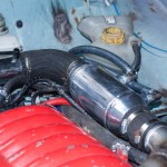
The chargecooler was also put into place, and have begun to plumb it in.
We also spent some time moving my dad's ramp from one side of the garage to the other - with the new roof we fitted last year, this now allows us to get the car much higher off the ground - and can now stand underneath it, rather than having to crawl under it! This will help when we do the remaining welding under the car which will need to be done prior to thinking about putting it on the road.
This involved running 2x lines from the master cylinder to the servos in the boot, and from the servos, out to each of the 4 wheels.
Taking cues from modern vehicles, we are installing dual circuits, splitting the circuits diagonally across the car.
One circuit is Left Front/Right Rear, the other is Right Front/Left Rear. By doing this, should there be an issue with one circuit, the other circuit should still be able to provide braking force, and by diagonally splitting the circuits, the braking is more balanced during these situations.
As I am using a combination of Escort calipers on the front, and 200SX calipers on the rear, I can't buy a flexible brake hose kit off the shelf, so took another trip to Hosequip where they made up some custom braided pipes with our choice of ends to suit our needs.
The chargecooler was also put into place, and have begun to plumb it in.
We also spent some time moving my dad's ramp from one side of the garage to the other - with the new roof we fitted last year, this now allows us to get the car much higher off the ground - and can now stand underneath it, rather than having to crawl under it! This will help when we do the remaining welding under the car which will need to be done prior to thinking about putting it on the road.

-
Confused
- Posts: 749
- Joined: Fri Jan 27, 2012 11:44 am
- My Generation: 4G
- Location: Notts / Essex
- Has thanked: 3 times
- Been thanked: 11 times
- Contact:
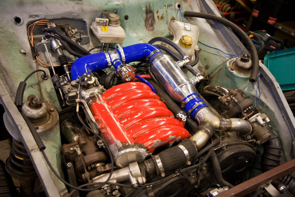
A lesson in Blow Off Valves
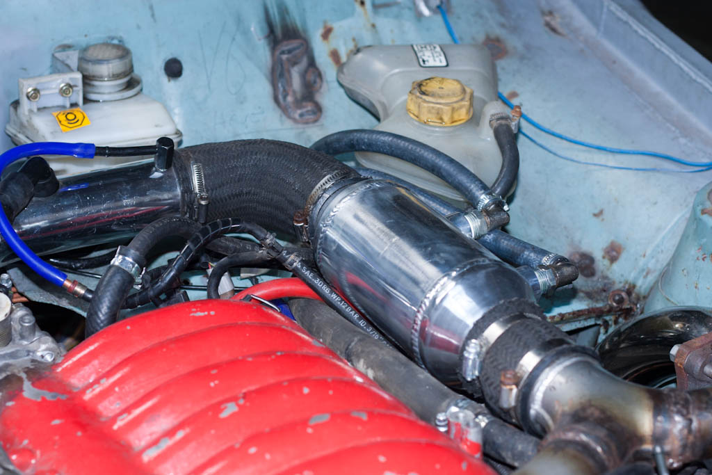
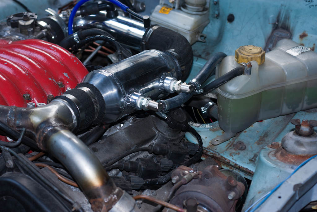
Last time, I managed to get as far as hooking up a couple of hoses from the chargecooler to the bulkhead.
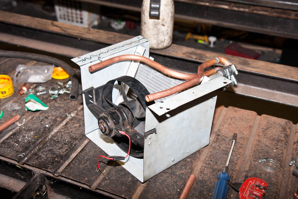
So the task this time was to complete the chargecooler circuit, which involved running pipework to the rear of the car, through the boot floor and to the radiator box, which still needed a bit more to easily hook up the pipes.

Forgot to take any images, but the chargecooler system is now completely plumbed up, including an old coolant header tank as a reservoir, and the pump is hooked up to the trigger for the fuel pump, so is running whenever the ignition is on. An adjustable temperature-activated switch is still to be installed, which will switch the fan on when the coolant temperature in the chargecooler circuit gets to a specific temperature - which is yet to be decided!
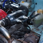
Having had a bit of temporary pipe on the inlet, which had to be bunged up with an old injector, it was time to change this to a proper bit of pipe, with the correct outlets on it - such as for a blow-off valve (BOV - also known as a dump valve, or diverter valve)
The job of the BOV is to relieve excess pressure in the intake when the throttle is closed.
When you accelerate a turbo'd engine, the exhaust gasses drive the turbine on the turbo, which in turn drives the compressor on the turbo, which takes air at atmospheric pressure, and compresses it to a higher pressure - the standard TD-03 turbos on the 6A13TT will compress the air to about 10 PSI above atmospheric pressure (which is 14.5 PSI). Once compressed, there are more oxygen molecules in a given volume, and this allows more fuel to be introduced, which creates a bigger bang in the engine, and therefore more power (and more exhaust gasses) - the process repeats over and over.
With the throttle body open, this compressed air will get forced into the cylinders in the engine. When you stop accelerating, you close the throttle body, and there is now nowhere for this compressed air to go. The turbo continues spinning for a small amount of time after you stop accelerating, which continues to compress the incoming air - trying to add to the compressed air already in the inlet pipework between the turbo and the throttle body.
If there were no BOV, then this compressed air would try to equalise pressure by the easiest possible route - which would be to try to go back out through the compressor of the turbo - this can cause the compressor of the turbo to be attempting to compress the air, whilst the already compressed air is trying to come back the other way - causing the compressor wheel (and, because they are linked, the turbine wheel) to stop turning, or even attempt to turn the opposite way (fighting against the exhaust gasses still trying to turn the turbine the correct way) - this can cause a "fluttering" noise. This is also known as compressor surge.
You can hear it a bit in my previous videos, but the following video also shows it off well:
[youtube]LZUbo_mNDZM[/youtube]
To prevent this, the BOV is installed in the inlet pipework after the turbo, and before the throttle body. This is a large valve, operated by a diaphragm, which has a spring inside to hold it closed, as well as a vacuum/pressure pipe which is attached to the manifold (after the throttle body) - when the turbo is producing a positive pressure in the intake manifold, this pressure also assists in keeping the BOV closed by pushing against the diaphragm. Spring + compressed air pressure on one side of the diaphragm is a larger force than the compressed air pressure in the intake pipework.
When you close the throttle body, the intake manifold then goes into a vacuum, which pulls against the diaphragm - this vacuum, combined with the positive pressure of the intake pipework, allows the valve to open - giving the compressed air in the intake pipework an easy route to escape, without going back through the turbo compressor wheel.
On most production cars, this is routed back into the intake *before* the turbo - a recirculating valve. Especially where a MAF (Mass Airflow Sensor) is used, where the air has already been accounted for by the engine ECU. It is less of an issue where a MAP (Manifold Absolute Pressure) sensor is in use, because this air has not been accounted for yet by the ECU.
The Anglia has no pipework before the turbos to route this air to - therefore the BOV used is a Vent To Atmosphere (VTA) one. A VTA BOV is what gives the "pssssstthhhh" noise that you associate with a turbo car.
(the picture was taken before I'd attached the small blue vacuum pipe to the BOV - this is what attaches to the manifold)
With the inlet pipework and BOV now correctly hooked up - there is no loss of pressure in the inlet any more, and a small touch of the throttle causes the boost to climb quite quickly! It'll be fun to drive...!
So the task this time was to complete the chargecooler circuit, which involved running pipework to the rear of the car, through the boot floor and to the radiator box, which still needed a bit more to easily hook up the pipes.
Forgot to take any images, but the chargecooler system is now completely plumbed up, including an old coolant header tank as a reservoir, and the pump is hooked up to the trigger for the fuel pump, so is running whenever the ignition is on. An adjustable temperature-activated switch is still to be installed, which will switch the fan on when the coolant temperature in the chargecooler circuit gets to a specific temperature - which is yet to be decided!
Having had a bit of temporary pipe on the inlet, which had to be bunged up with an old injector, it was time to change this to a proper bit of pipe, with the correct outlets on it - such as for a blow-off valve (BOV - also known as a dump valve, or diverter valve)
The job of the BOV is to relieve excess pressure in the intake when the throttle is closed.
When you accelerate a turbo'd engine, the exhaust gasses drive the turbine on the turbo, which in turn drives the compressor on the turbo, which takes air at atmospheric pressure, and compresses it to a higher pressure - the standard TD-03 turbos on the 6A13TT will compress the air to about 10 PSI above atmospheric pressure (which is 14.5 PSI). Once compressed, there are more oxygen molecules in a given volume, and this allows more fuel to be introduced, which creates a bigger bang in the engine, and therefore more power (and more exhaust gasses) - the process repeats over and over.
With the throttle body open, this compressed air will get forced into the cylinders in the engine. When you stop accelerating, you close the throttle body, and there is now nowhere for this compressed air to go. The turbo continues spinning for a small amount of time after you stop accelerating, which continues to compress the incoming air - trying to add to the compressed air already in the inlet pipework between the turbo and the throttle body.
If there were no BOV, then this compressed air would try to equalise pressure by the easiest possible route - which would be to try to go back out through the compressor of the turbo - this can cause the compressor of the turbo to be attempting to compress the air, whilst the already compressed air is trying to come back the other way - causing the compressor wheel (and, because they are linked, the turbine wheel) to stop turning, or even attempt to turn the opposite way (fighting against the exhaust gasses still trying to turn the turbine the correct way) - this can cause a "fluttering" noise. This is also known as compressor surge.
You can hear it a bit in my previous videos, but the following video also shows it off well:
[youtube]LZUbo_mNDZM[/youtube]
To prevent this, the BOV is installed in the inlet pipework after the turbo, and before the throttle body. This is a large valve, operated by a diaphragm, which has a spring inside to hold it closed, as well as a vacuum/pressure pipe which is attached to the manifold (after the throttle body) - when the turbo is producing a positive pressure in the intake manifold, this pressure also assists in keeping the BOV closed by pushing against the diaphragm. Spring + compressed air pressure on one side of the diaphragm is a larger force than the compressed air pressure in the intake pipework.
When you close the throttle body, the intake manifold then goes into a vacuum, which pulls against the diaphragm - this vacuum, combined with the positive pressure of the intake pipework, allows the valve to open - giving the compressed air in the intake pipework an easy route to escape, without going back through the turbo compressor wheel.
On most production cars, this is routed back into the intake *before* the turbo - a recirculating valve. Especially where a MAF (Mass Airflow Sensor) is used, where the air has already been accounted for by the engine ECU. It is less of an issue where a MAP (Manifold Absolute Pressure) sensor is in use, because this air has not been accounted for yet by the ECU.
The Anglia has no pipework before the turbos to route this air to - therefore the BOV used is a Vent To Atmosphere (VTA) one. A VTA BOV is what gives the "pssssstthhhh" noise that you associate with a turbo car.
(the picture was taken before I'd attached the small blue vacuum pipe to the BOV - this is what attaches to the manifold)
With the inlet pipework and BOV now correctly hooked up - there is no loss of pressure in the inlet any more, and a small touch of the throttle causes the boost to climb quite quickly! It'll be fun to drive...!
-
Confused
- Posts: 749
- Joined: Fri Jan 27, 2012 11:44 am
- My Generation: 4G
- Location: Notts / Essex
- Has thanked: 3 times
- Been thanked: 11 times
- Contact:
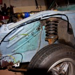
Front suspension polybushing
Just a quick update this time round! Have been doing some work on the front suspension, replacing the existing rubber bushes on the track control arms with new polyurethane one. The old bushes had so much play in them, the front suspension geometry was all over the place. With the new bushes, the front end has no excess play, and the tracking can be set accordingly.
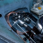
Also spent some more time on wiring - still a fair bit to tidy up, and every little helps, even if it doesn't look like there's been any progress!
Also spent some more time on wiring - still a fair bit to tidy up, and every little helps, even if it doesn't look like there's been any progress!
-
Confused
- Posts: 749
- Joined: Fri Jan 27, 2012 11:44 am
- My Generation: 4G
- Location: Notts / Essex
- Has thanked: 3 times
- Been thanked: 11 times
- Contact:
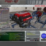
An Automation Simulation
A couple of months ago, I came across an interesting game which is still very early in development, that rather piqued my curiosity.
The game is Automation: The Car Tycoon Game - the premise is that you start off post-war (1946) as a budding car designer/maker, and you need to design and build cars, progressing through time, making new models, utilising new technology and generally trying to make as much money as possible.
Whilst this sounds fairly cool, the "tycoon" part of the game isn't made yet. When I first saw it, it was basically an engine creator - allowing you to make Inline 4, Inline 6, and V8 (crossplane & flatplane) engines, both naturally aspirated and turbo. Unfortunately, no V6 engines yet... (can you see where this might be going...)
A recently released update adds a number of features to the car designer, mostly around wheel/tyre, brakes and suspension, as well as adding a number of new performance statistics which are updated based on the options you choose.
So, what better than to get a few ideas on performance on something that's rather similar to what I'm actually building!
So, first off, I present the 8A13TT engine - the 6A13TT engine has a 81mm bore and 80.8mm stroke giving 2498cc - my 8 cylinder engine is also 2498cc, with a 73.6mm bore and 73.4mm stroke to achieve it (following the V6's 0.2mm difference between bore and stroke)
The goal is ~276bhp and ~260lb-ft torque, so let's spend a few minutes making it:
Not too bad On the 6A13TT, the peak torque comes in a little earlier, and holds a bit higher towards the red-line - but close enough for now!
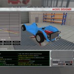
So, onto the next part, which is designing a vehicle for it to go into. There's a number of body styles available, but nothing that will allow me to make the unique shape of the Anglia, so I've settled for something that looks a little more like a Mk2 Escort.
Whilst the body shape is important in Automation to the aerodynamics, and subsequently the performance, neither an Escort or an Anglia are the most aerodynamic of cars out there, so we'll take the estimations as just that, and instead concentrate on the meat that I'm interested in - that being suspension and tyres.
For this, I've chosen MacPherson strut for the front end, to mimic the Escort setup I'm using, and I've selected the "solid axle coil" to represent the rear - my De-Dion acts most like a solid axle in terms of bounce and roll, it just doesn't have the heavy diff in the middle.
You can specify camber (in degrees), spring stiffness (in Newtons per meter, 25000 N/m = ~140 lbs/in for those of you who work in old money), damper rate (in Newton-seconds per meter), and anti-roll bar stiffness (in Nm/rad, Newton-meters per radian)
I've currently got 140lb springs on the rear, and I have put an estimate of 200lb springs on the front, based on what I've seen people using on other vehicles with heavier engines up front - so these have been plugged into Automation.
These suspension settings will give you results for roll, weight transfer, body bump, and when matched with wheels/tyres (where you can specify wheel diameter, tyre size and compound) will also affect acceleration and cornering.
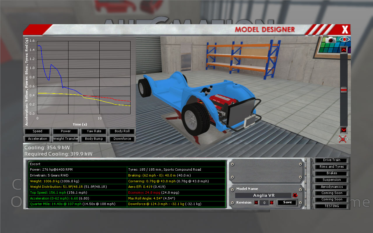
So - by putting in some known values from what I will be using (13" wheels, 185/60 tyres), along with the engine/gearbox settings (5 gears, top theoretical speed based on gearing of ~160mph) and an overall weight (I've chosen 1000kg) and weight distribution (roughly 50/50) - my dad's 4WD Anglia weighs 980kg and has near perfect 50/50 weight distribution, so a good baseline.
Putting all of that together gives the following results:
Some key points without enlarging the image:
0-62mph: 6.4 seconds
1/4 mile: 14.3 seconds @ 109mph
There's a number of graphs, but I've put up an interesting one in the image - the Acceleration graph. The blue line shows that it calculates that in the first 3 gears, I will have too much power for the tyres to cope with. It's not until I hit 4th gear at approximately 7 seconds that I'll have enough grip to utilise the full power of the engine.
Obviously, here's where everyone jumps in and tells me that of course, the engine is too powerful for the car, and that I'm doing it all wrong.
However, where's the fun in that?
The game is Automation: The Car Tycoon Game - the premise is that you start off post-war (1946) as a budding car designer/maker, and you need to design and build cars, progressing through time, making new models, utilising new technology and generally trying to make as much money as possible.
Whilst this sounds fairly cool, the "tycoon" part of the game isn't made yet. When I first saw it, it was basically an engine creator - allowing you to make Inline 4, Inline 6, and V8 (crossplane & flatplane) engines, both naturally aspirated and turbo. Unfortunately, no V6 engines yet... (can you see where this might be going...)
A recently released update adds a number of features to the car designer, mostly around wheel/tyre, brakes and suspension, as well as adding a number of new performance statistics which are updated based on the options you choose.
So, what better than to get a few ideas on performance on something that's rather similar to what I'm actually building!
So, first off, I present the 8A13TT engine - the 6A13TT engine has a 81mm bore and 80.8mm stroke giving 2498cc - my 8 cylinder engine is also 2498cc, with a 73.6mm bore and 73.4mm stroke to achieve it (following the V6's 0.2mm difference between bore and stroke)
The goal is ~276bhp and ~260lb-ft torque, so let's spend a few minutes making it:

Not too bad
So, onto the next part, which is designing a vehicle for it to go into. There's a number of body styles available, but nothing that will allow me to make the unique shape of the Anglia, so I've settled for something that looks a little more like a Mk2 Escort.
Whilst the body shape is important in Automation to the aerodynamics, and subsequently the performance, neither an Escort or an Anglia are the most aerodynamic of cars out there, so we'll take the estimations as just that, and instead concentrate on the meat that I'm interested in - that being suspension and tyres.
For this, I've chosen MacPherson strut for the front end, to mimic the Escort setup I'm using, and I've selected the "solid axle coil" to represent the rear - my De-Dion acts most like a solid axle in terms of bounce and roll, it just doesn't have the heavy diff in the middle.
You can specify camber (in degrees), spring stiffness (in Newtons per meter, 25000 N/m = ~140 lbs/in for those of you who work in old money), damper rate (in Newton-seconds per meter), and anti-roll bar stiffness (in Nm/rad, Newton-meters per radian)
I've currently got 140lb springs on the rear, and I have put an estimate of 200lb springs on the front, based on what I've seen people using on other vehicles with heavier engines up front - so these have been plugged into Automation.
These suspension settings will give you results for roll, weight transfer, body bump, and when matched with wheels/tyres (where you can specify wheel diameter, tyre size and compound) will also affect acceleration and cornering.
So - by putting in some known values from what I will be using (13" wheels, 185/60 tyres), along with the engine/gearbox settings (5 gears, top theoretical speed based on gearing of ~160mph) and an overall weight (I've chosen 1000kg) and weight distribution (roughly 50/50) - my dad's 4WD Anglia weighs 980kg and has near perfect 50/50 weight distribution, so a good baseline.
Putting all of that together gives the following results:
Some key points without enlarging the image:
0-62mph: 6.4 seconds
1/4 mile: 14.3 seconds @ 109mph
There's a number of graphs, but I've put up an interesting one in the image - the Acceleration graph. The blue line shows that it calculates that in the first 3 gears, I will have too much power for the tyres to cope with. It's not until I hit 4th gear at approximately 7 seconds that I'll have enough grip to utilise the full power of the engine.
Obviously, here's where everyone jumps in and tells me that of course, the engine is too powerful for the car, and that I'm doing it all wrong.
However, where's the fun in that?
-
RattyMcClelland

- Moderator
- Posts: 9208
- Joined: Wed Aug 04, 2010 10:02 pm
- My Generation: 5G
- PSN GamerTag: RattyMcClelland
- Location: Leicestershire
- Been thanked: 203 times

-
Confused
- Posts: 749
- Joined: Fri Jan 27, 2012 11:44 am
- My Generation: 4G
- Location: Notts / Essex
- Has thanked: 3 times
- Been thanked: 11 times
- Contact:
Lights, Camera, Picture
More wiring! More headaches!
Other than general tidying and removal of extra length, the main thing that needs sorting now wiring wise is for about the only electrical systems left on the vehicle - lights, horn and wiper!
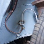
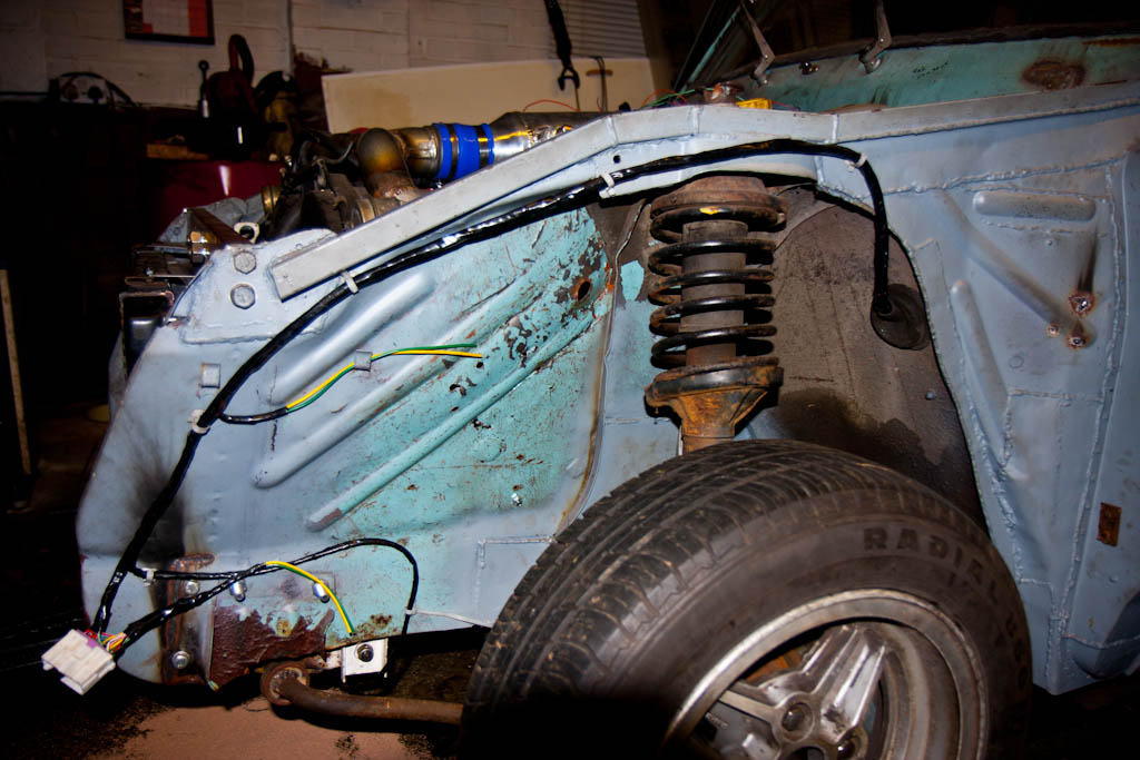
So - onto those then! Wiring for horn + front lights was identified, tidied, routed, loomed and affixed:
With a nice connector plug ready to make removal of the fibreglass flip front (which has been ordered, awaiting delivery) as simple as possible.
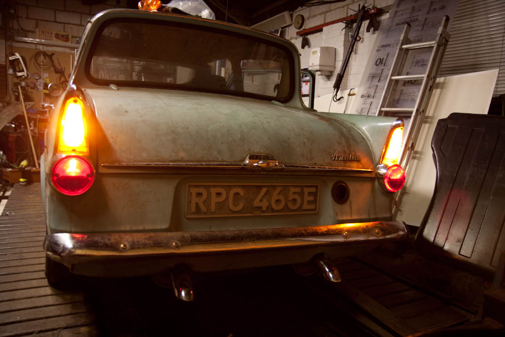
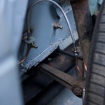
And the rear lights were dug out of storage, bulbs checked and replaced where necessary, and wired up, including tidying up and re-looming the run of wires to the rear:

Other than general tidying and removal of extra length, the main thing that needs sorting now wiring wise is for about the only electrical systems left on the vehicle - lights, horn and wiper!
So - onto those then! Wiring for horn + front lights was identified, tidied, routed, loomed and affixed:
With a nice connector plug ready to make removal of the fibreglass flip front (which has been ordered, awaiting delivery) as simple as possible.
And the rear lights were dug out of storage, bulbs checked and replaced where necessary, and wired up, including tidying up and re-looming the run of wires to the rear: