
X2 to thisMerlin wrote:Where did you get your black hoses from and how much did they cost?
Congratulations to vtecmec for winning May/June's Lude Of The Month, with his DIY Turbo BB1 build.
>>> Click Here For Profile <<<

>>> Click Here For Profile <<<
Supercharged Mugen Lude (03/06/14 Update!)
-
Thebusofwoe

- Supporter 2014
- Posts: 2670
- Joined: Mon Mar 11, 2013 11:47 pm
- My Generation: 4G
- Location: Salisbury, Wiltshire
- Been thanked: 2 times
One life, LIVE IT! Get VTEC, LOVE it. Drive a Honda and ENJOY it.
Build thread : http://www.ludegeneration.co.uk/profile ... t7849.html
Build thread : http://www.ludegeneration.co.uk/profile ... t7849.html
-
nellers2001
- Posts: 80
- Joined: Sun Jan 29, 2012 11:17 pm
- My Generation: 4G
- Location: Cardiff
I had a nightmare with the aluminium japspeed rad for my 4th gen a couple years back. Emailed japspeed to tell them they don't fit and they basically said they didn't care as never had a complaint before...I found that very hard to believe but had already modified the mountings on the car with a grinder to make it fit!
-
NafemanNathan

- LotM Winner
- Posts: 20144
- Joined: Sun Aug 08, 2010 9:37 pm
- My Generation: 0G
- Location: Yeovil, Somerset
- Has thanked: 8 times
- Been thanked: 124 times
This is the best price I've found for them (Been in my basket for the past two yearsThebusofwoe wrote:X2 to thisMerlin wrote:Where did you get your black hoses from and how much did they cost?
http://www.dcperformance.co.uk/cheap/27 ... -97bk.html
Nice few bits and bobs as usual Rob

-
nucleustylzlude

- Moderator
- Posts: 4013
- Joined: Wed Aug 11, 2010 11:46 pm
- My Generation: 4G
- Location: Bristol, UK!
- Been thanked: 7 times
- Contact:
 Re: Supercharged Mugen Lude (23/05/14 Update!)
You can get them from a few places but I got mine where I get everything - EBay! New old stock clearance. Instead of the £80 plus price tag I paid just over a third.Thebusofwoe wrote:X2 to thisMerlin wrote:Where did you get your black hoses from and how much did they cost?
I'm loving the block too! Gonna give me room to relax if the engine goes bang one day. Yeah Nathan and 4thgenphil both have some Spoon mirrors with DC2 base plates and they say the shape is near perfect for our ludes. All Civic ones are way off! As for where to get them, US eBay and Amazon, £30-50 for ABS plastic and a little more for carbon ones.ddoubledanny wrote:
Also I've been looking for some spoon mirrors for ages so might give that ago do you know where i could buy them cheers bud
When did you see my bits?mercutio wrote:great bits rob
Sounds about right, exactly what I need to do is get the grinder out. Heard many people say about the fitment issues but it's still well made and I can't deny the huge capacity of it.nellers2001 wrote:I had a nightmare with the aluminium japspeed rad for my 4th gen a couple years back. Emailed japspeed to tell them they don't fit and they basically said they didn't care as never had a complaint before...I found that very hard to believe but had already modified the mountings on the car with a grinder to make it fit!

-
nucleustylzlude
- Moderator
- Posts: 4013
- Joined: Wed Aug 11, 2010 11:46 pm
- My Generation: 4G
- Location: Bristol, UK!
- Been thanked: 7 times
- Contact:
Re: Supercharged Mugen Lude (23/05/14 Update!)
That is the best retail I've seen but you know me I buy low sell high!NafemanNathan wrote:This is the best price I've found for them (Been in my basket for the past two yearsThebusofwoe wrote:X2 to thisMerlin wrote:Where did you get your black hoses from and how much did they cost?
)...
http://www.dcperformance.co.uk/cheap/27 ... -97bk.html
Nice few bits and bobs as usual Rob
What did you buy off him in the end Nath?
-
NafemanNathan
- LotM Winner
- Posts: 20144
- Joined: Sun Aug 08, 2010 9:37 pm
- My Generation: 0G
- Location: Yeovil, Somerset
- Has thanked: 8 times
- Been thanked: 124 times
-
nucleustylzlude
- Moderator
- Posts: 4013
- Joined: Wed Aug 11, 2010 11:46 pm
- My Generation: 4G
- Location: Bristol, UK!
- Been thanked: 7 times
- Contact:
Re: Supercharged Mugen Lude (23/05/14 Update!)
Can't believe you got the bearings! I enquired and he said he couldn't find them. I guess you gave him a better offer!
Plus I can't win them all!
-
NafemanNathan
- LotM Winner
- Posts: 20144
- Joined: Sun Aug 08, 2010 9:37 pm
- My Generation: 0G
- Location: Yeovil, Somerset
- Has thanked: 8 times
- Been thanked: 124 times
-
nucleustylzlude
- Moderator
- Posts: 4013
- Joined: Wed Aug 11, 2010 11:46 pm
- My Generation: 4G
- Location: Bristol, UK!
- Been thanked: 7 times
- Contact:
Re: Supercharged Mugen Lude (23/05/14 Update!)
His way of dealing with the politics I guess. Still can't complain what I managed to get.
-
nucleustylzlude
- Moderator
- Posts: 4013
- Joined: Wed Aug 11, 2010 11:46 pm
- My Generation: 4G
- Location: Bristol, UK!
- Been thanked: 7 times
- Contact:
BUILD PART 5) - Build (Cont'd) – Electrical Bits
BUILD PART 5) - Build (Cont'd) – Electrical Bits
Battery Relocation & Additions
Well, a while back in my build thread I started the battery relocation, mostly consisting of removing everything battery related and the main wiring. I hadn’t gone onto the battery and wiring as there was various mechanical things to work on which is easier with nothing in the engine bay.
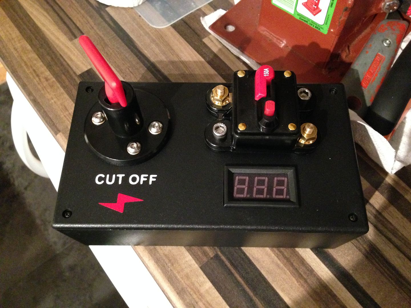
So roll on to this year and I’ve been busy with a project or two in the house on some evenings. The first was some kind of box to attach to the battery holder to house a battery cut off switch, a circuit breaker and a voltage tester (all ebay purchases as usual). One plastic PCB board holding box later from Maplins and some trimming here and there, plus some S/S bolts I have and I got it to this:
I tried it attached to the battery mount and it didn’t quite work, so I flipped it round and redid the labels:
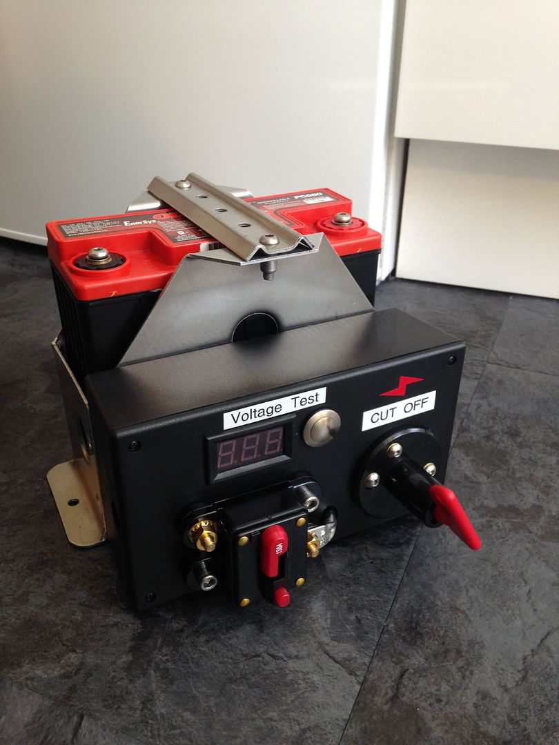
Also added a touch button for the voltage tester and the cable from cut-off to circuit breaker.
That was as far as I could take it in the house, so out to the garage – an actual trip to the garage to work on the car!!!
Firstly I got organised and then part way through I realised that was a waste of time:
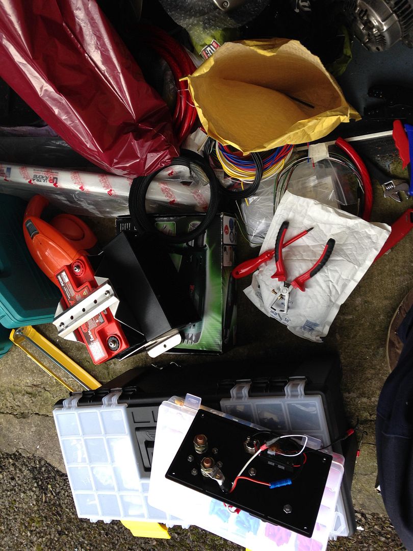
There really is no tidy way of working on electrics.
Here is the rear wiring if someone wants to try and replicate some of it:
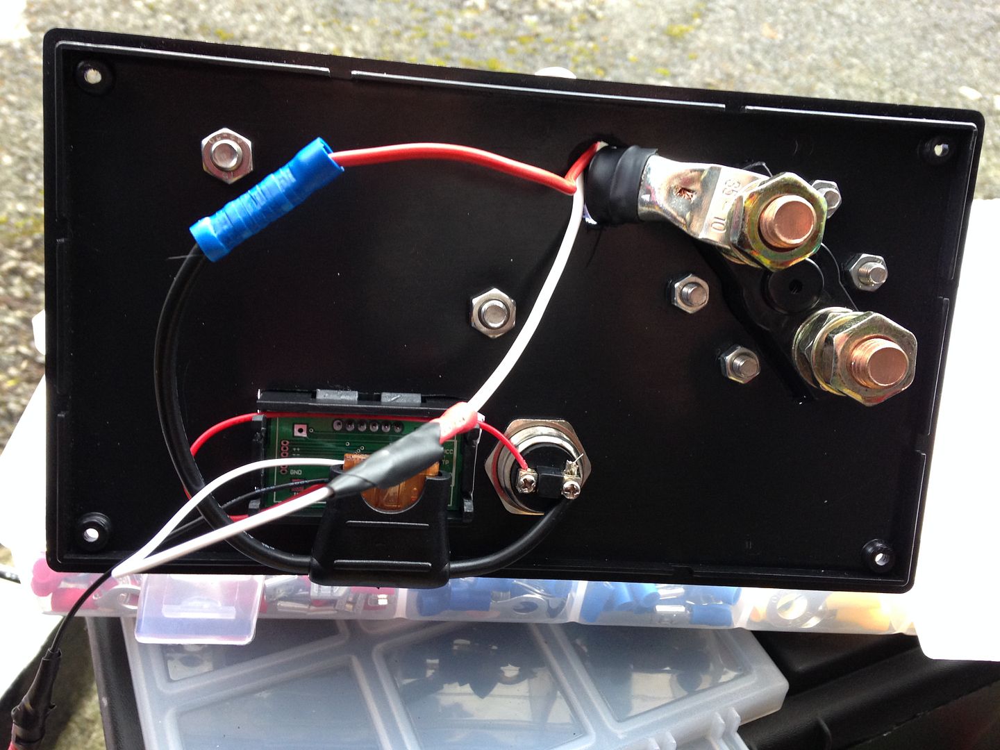
Hard to make out, but the tester goes as follows:
- Big chunky cable is the main power feed from battery through the cut-off switch to the circuit breaker. So I decided to use the bolt of the circuit breaker to take the power for the voltage tester and the voltage feed for the tester – no problems doing this.
- White wire from tester is the voltage feed to display which goes through the hole to the power side of circuit breaker.
- Red wire from voltage tester is the +ve power supply to the tester, this is fed straight to the switch (momentary push switch), out the other side to an inline fuse (5amps I think – overkill for such a tiny device). Then this continues through the hole to the power side of the circuit breaker.
- Black wire from voltage tester is the –ve ground for the tester circuit, this is fed out the side of the box and to the –ve terminal of the battery.
Pretty simple stuff and very handy to check the battery holding charge at different intervals.
I got it all hooked up to the battery with a 0 gauge cable, some braiding and heat shrink onto the ends of the terminals which came out better than I’d hoped it would.
Pretty cool. And voltage tester moment of glory – it works!
Then I bolted it down in the boot:
Most people stick it on the passenger side to aid weight distribution, I mainly went with this location as I havn’t ruled out water injection and the tank and gubbins can sit on the other side. Plus the cable routing should be less on this side as I have a limited length of 0 Gauge and it’s not cheap.
Next up is to run the +ve cable from the circuit breaker to the bulkhead connector:
It’s pretty bulky (hee hee!) at around 1 ¾” diameter. I’ve had a route around to see if I can use any existing holes and they’re all too small. My only hope is the old A/C pipes hole in front of the evaporator unit behind the dash, here:
I need to get the evap unit removed ASAP before I put my new seats back in – returned cleaned courtesy of Dan at Viper Valets.
So I’ll see what room I have to work with if this will work.
Other option is to use one of two existing holes I have but drill it one of them out bigger. There is one next to the A/C pipes, you can see it in the pic with the bung removed – this is around 20mm diameter. Or I have removed the cruise control cable which leaves an odd shaped hole smaller than 20mm. This one would be ideal for routing the cable most efficiently and hidden but not sure I can get one of the stepper drill bits in there.
Gauges
Next up I’ve also been tinkering in the house wiring all my gauges ready to install in the car.
I have 4 gauges at present with a mix of brands and look – surprisingly they don’t look too odd together. I have:
- AEM UEGO Wideband Gauge
- Dynotune Boost Gauge
- JRSC (Auto Meter) Oil Pressure Gauge (electrical)
- Auto Gauge Oil Temperature Gauge (electrical)
I fitted the first gauge the AEM in the tweeter location – it’s a perfect fit for a 52mm gauge. Forgot to take a pic of this, I’ll add it later.
The remaining three are in my custom A-pillar triple pod:
The wiring behind:
Probably best to draw up a diagram if people are wondering, but here’s a description of how I wired them in.
Circuit 1 +ve Power
AEM UEGO Gauge - A dedicated power supply is recommended in the installation instructions. Some tuning sellers recommend taking the power and ground from the same locations as the ECU, but I’m sceptical actually how much this will affect the gauges readings. I’m taking the power straight from the interior fuse box and the ECU receives power from here, so I think that’s close enough. It especially says not to ‘daisy chain the supplies with other gauges. I used an 'add-a-fuse' like this:
http://www.ebay.co.uk/itm/2-Add-A-Circu ... 0709632237
The gauge's instructions state it needs a 10 amp fuse and therefore I should use approximately 14-16 gauge cable (or 1.5-2.0mm2 to us Metric people). I have 2.00mm2 which handles up to 17.5amps. Rule of thumb is that you want the cable to exceed the fuse so you don’t melt the cable instead of the fuse strip. To be honest though, the current this gauge draws, this cabling is a little OTT, but I had some, so used it. This feeds from the gauge down to the add-a-fuse, which is installed into a spare location on the fuse board.
Circuit 2 +ve Power
3 remaining gauges – Again, these run off another 'add-a-fuse'. The Autometer gauges instructions recommend about 4-5amp fused connection, which will be about the same for each gauge. So I simply daisy chained these three gauges power supply to a 5amp fuse and used 1.0mm2 (16 guage) cable which is good for 8.75amps. I assume the daisy chaining will be fine for 3 gauges and the supply fuses and cable thicknesses I've used. I see them wired this way all the time.
Light Power)
Only two of these gauges have individual light +ve supplies, the JRSC (Auto Meter) Oil Pressue and the Auto Gauge Oil Pressure. I went with the simple solution of just having the lights on all the time, especially as one of them is a smoked face. Therefore you just connect the light supply together with the power supply. Simples! The other two gauges are fully digital and do not need light supplies.
Earth –ve Supply
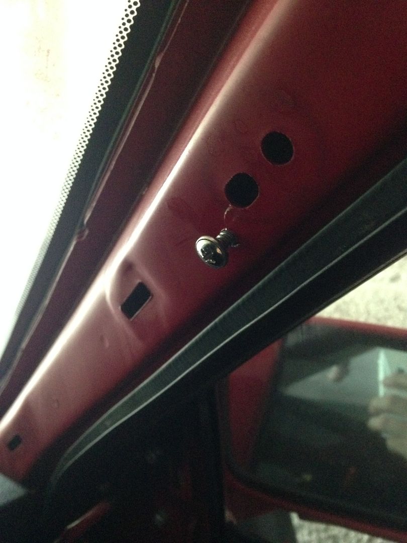
Seeing as most of these gauges are near the main chassis body, I simply drilled and tapped two holes in the A-pillar to create a –ve ground, one for the AEM and one for the other three, see here:
Other Wiring – Sensors & Outputs
Only things left to route to the engine bay / ECU from the footwell is the sensors wiring and the AEM’s wideband reading output which can be tapped into the P13 ECU (via the ELD pin) for my Hondata to read the wideband readings on datalogging. The main sensor lead to the Bosch wideband sensor has a pretty chunky plug, so you need to find a sizable hole to get it through. The boost gauge also has a wiring lead to the boost reading device to place in the engine bay, which connects to a vacuum port with some hosing. The two small wires for the oil temp and pressure will be run off the same locations as Merlin placed his as it had some good advice from the oracle at Performance Autoworks.
Here is a good link I found helpful:
- http://www.autoelectricsupplies.co.uk/ - I got all my cabling from here, plus some terminals and stuff. Goof info on cable size, amp limits, etc.
That’s it for this update, writing some more to post again soon.
Cheers,
Rob
Battery Relocation & Additions
Well, a while back in my build thread I started the battery relocation, mostly consisting of removing everything battery related and the main wiring. I hadn’t gone onto the battery and wiring as there was various mechanical things to work on which is easier with nothing in the engine bay.
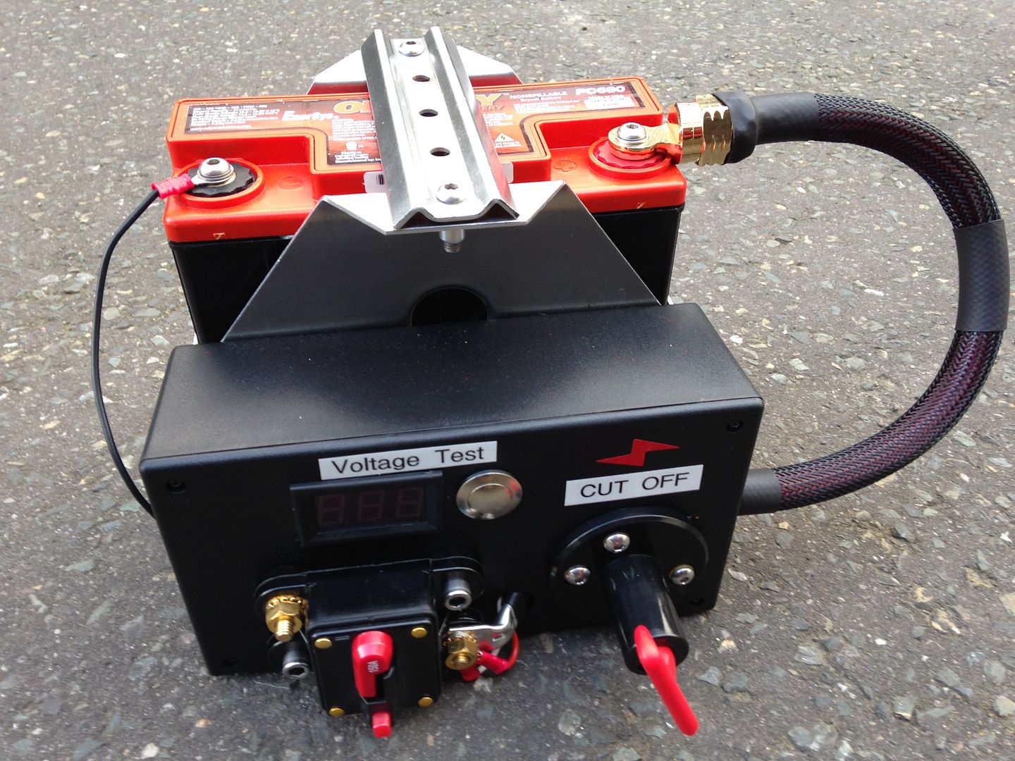
So roll on to this year and I’ve been busy with a project or two in the house on some evenings. The first was some kind of box to attach to the battery holder to house a battery cut off switch, a circuit breaker and a voltage tester (all ebay purchases as usual). One plastic PCB board holding box later from Maplins and some trimming here and there, plus some S/S bolts I have and I got it to this:

I tried it attached to the battery mount and it didn’t quite work, so I flipped it round and redid the labels:

Also added a touch button for the voltage tester and the cable from cut-off to circuit breaker.
That was as far as I could take it in the house, so out to the garage – an actual trip to the garage to work on the car!!!
Firstly I got organised and then part way through I realised that was a waste of time:

There really is no tidy way of working on electrics.
Here is the rear wiring if someone wants to try and replicate some of it:

Hard to make out, but the tester goes as follows:
- Big chunky cable is the main power feed from battery through the cut-off switch to the circuit breaker. So I decided to use the bolt of the circuit breaker to take the power for the voltage tester and the voltage feed for the tester – no problems doing this.
- White wire from tester is the voltage feed to display which goes through the hole to the power side of circuit breaker.
- Red wire from voltage tester is the +ve power supply to the tester, this is fed straight to the switch (momentary push switch), out the other side to an inline fuse (5amps I think – overkill for such a tiny device). Then this continues through the hole to the power side of the circuit breaker.
- Black wire from voltage tester is the –ve ground for the tester circuit, this is fed out the side of the box and to the –ve terminal of the battery.
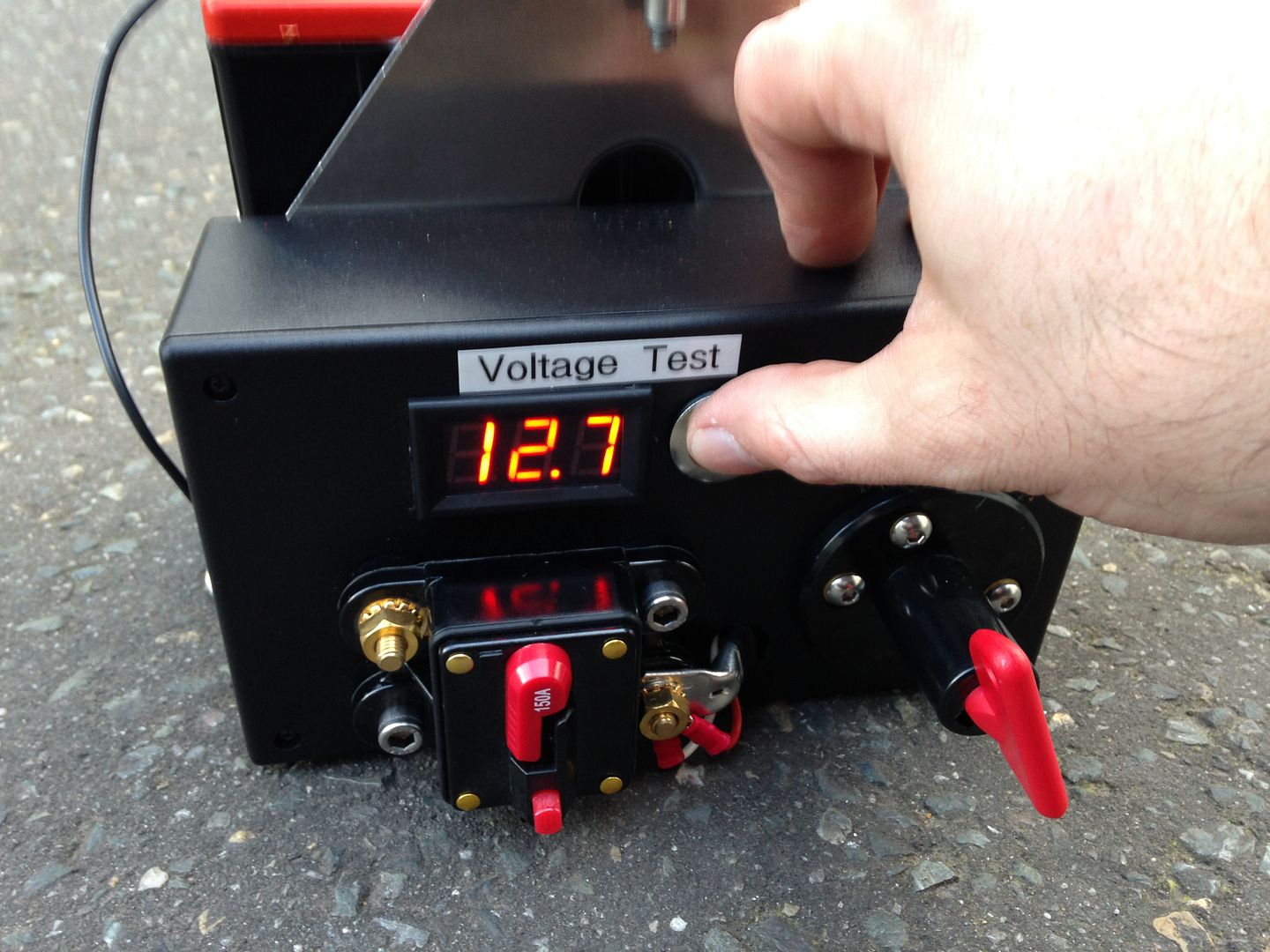
Pretty simple stuff and very handy to check the battery holding charge at different intervals.
I got it all hooked up to the battery with a 0 gauge cable, some braiding and heat shrink onto the ends of the terminals which came out better than I’d hoped it would.

Pretty cool. And voltage tester moment of glory – it works!

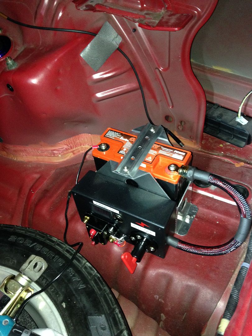
Then I bolted it down in the boot:

Most people stick it on the passenger side to aid weight distribution, I mainly went with this location as I havn’t ruled out water injection and the tank and gubbins can sit on the other side. Plus the cable routing should be less on this side as I have a limited length of 0 Gauge and it’s not cheap.
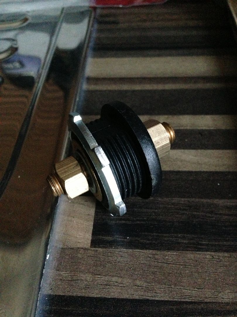
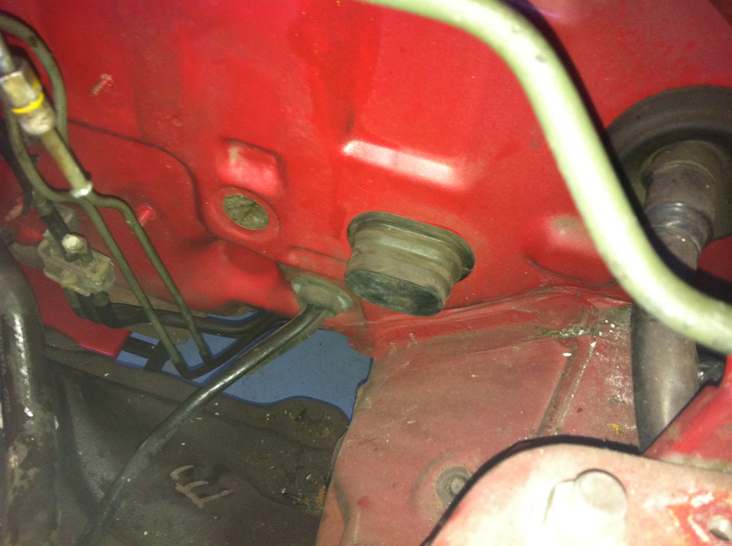
Next up is to run the +ve cable from the circuit breaker to the bulkhead connector:

It’s pretty bulky (hee hee!) at around 1 ¾” diameter. I’ve had a route around to see if I can use any existing holes and they’re all too small. My only hope is the old A/C pipes hole in front of the evaporator unit behind the dash, here:

I need to get the evap unit removed ASAP before I put my new seats back in – returned cleaned courtesy of Dan at Viper Valets.
So I’ll see what room I have to work with if this will work.
Other option is to use one of two existing holes I have but drill it one of them out bigger. There is one next to the A/C pipes, you can see it in the pic with the bung removed – this is around 20mm diameter. Or I have removed the cruise control cable which leaves an odd shaped hole smaller than 20mm. This one would be ideal for routing the cable most efficiently and hidden but not sure I can get one of the stepper drill bits in there.
Gauges
Next up I’ve also been tinkering in the house wiring all my gauges ready to install in the car.
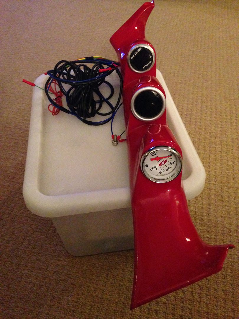
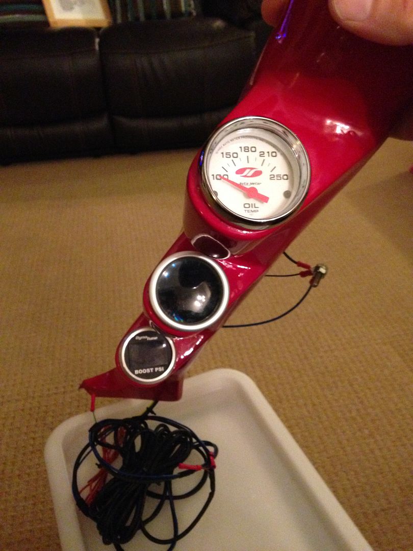
I have 4 gauges at present with a mix of brands and look – surprisingly they don’t look too odd together. I have:
- AEM UEGO Wideband Gauge
- Dynotune Boost Gauge
- JRSC (Auto Meter) Oil Pressure Gauge (electrical)
- Auto Gauge Oil Temperature Gauge (electrical)
I fitted the first gauge the AEM in the tweeter location – it’s a perfect fit for a 52mm gauge. Forgot to take a pic of this, I’ll add it later.
The remaining three are in my custom A-pillar triple pod:


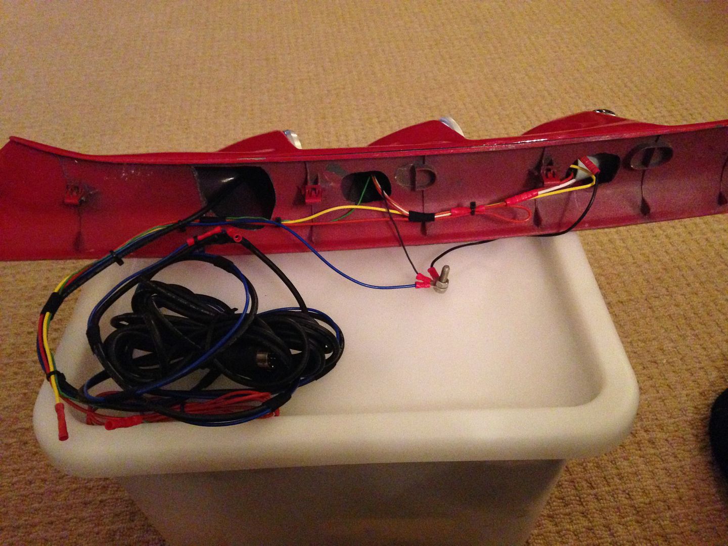
The wiring behind:

Probably best to draw up a diagram if people are wondering, but here’s a description of how I wired them in.
Circuit 1 +ve Power
AEM UEGO Gauge - A dedicated power supply is recommended in the installation instructions. Some tuning sellers recommend taking the power and ground from the same locations as the ECU, but I’m sceptical actually how much this will affect the gauges readings. I’m taking the power straight from the interior fuse box and the ECU receives power from here, so I think that’s close enough. It especially says not to ‘daisy chain the supplies with other gauges. I used an 'add-a-fuse' like this:
http://www.ebay.co.uk/itm/2-Add-A-Circu ... 0709632237
The gauge's instructions state it needs a 10 amp fuse and therefore I should use approximately 14-16 gauge cable (or 1.5-2.0mm2 to us Metric people). I have 2.00mm2 which handles up to 17.5amps. Rule of thumb is that you want the cable to exceed the fuse so you don’t melt the cable instead of the fuse strip. To be honest though, the current this gauge draws, this cabling is a little OTT, but I had some, so used it. This feeds from the gauge down to the add-a-fuse, which is installed into a spare location on the fuse board.
Circuit 2 +ve Power
3 remaining gauges – Again, these run off another 'add-a-fuse'. The Autometer gauges instructions recommend about 4-5amp fused connection, which will be about the same for each gauge. So I simply daisy chained these three gauges power supply to a 5amp fuse and used 1.0mm2 (16 guage) cable which is good for 8.75amps. I assume the daisy chaining will be fine for 3 gauges and the supply fuses and cable thicknesses I've used. I see them wired this way all the time.
Light Power)
Only two of these gauges have individual light +ve supplies, the JRSC (Auto Meter) Oil Pressue and the Auto Gauge Oil Pressure. I went with the simple solution of just having the lights on all the time, especially as one of them is a smoked face. Therefore you just connect the light supply together with the power supply. Simples! The other two gauges are fully digital and do not need light supplies.
Earth –ve Supply
Seeing as most of these gauges are near the main chassis body, I simply drilled and tapped two holes in the A-pillar to create a –ve ground, one for the AEM and one for the other three, see here:

Other Wiring – Sensors & Outputs
Only things left to route to the engine bay / ECU from the footwell is the sensors wiring and the AEM’s wideband reading output which can be tapped into the P13 ECU (via the ELD pin) for my Hondata to read the wideband readings on datalogging. The main sensor lead to the Bosch wideband sensor has a pretty chunky plug, so you need to find a sizable hole to get it through. The boost gauge also has a wiring lead to the boost reading device to place in the engine bay, which connects to a vacuum port with some hosing. The two small wires for the oil temp and pressure will be run off the same locations as Merlin placed his as it had some good advice from the oracle at Performance Autoworks.
Here is a good link I found helpful:
- http://www.autoelectricsupplies.co.uk/ - I got all my cabling from here, plus some terminals and stuff. Goof info on cable size, amp limits, etc.
That’s it for this update, writing some more to post again soon.
Cheers,
Rob