Congratulations to vtecmec for winning May/June's Lude Of The Month, with his DIY Turbo BB1 build.

>>> Click Here For Profile <<<

Image

Nathan's Road-Legal/Track BB4

Tell us all about your Lude, you know you want to ...
User avatar
NafemanNathan
LotM Winner
Posts: 20144
Joined: Sun Aug 08, 2010 9:37 pm
My Generation: 0G
Location: Yeovil, Somerset
Has thanked: 8 times
Been thanked: 124 times

Re: PLEASE DO NOT POST IN THIS THREAD YET (Under Constructio

Post by NafemanNathan » Tue Feb 07, 2012 9:20 am

Not quite :lol:

The throttle cable was sticking, but I just slackened it off a bit and sorted that after the ride home. But also the timing's out. The dizzy's full advanced, but she's still sluggish. Had the problem before the whole cambelt issue, but the effects weren't noticeable then.

Think I'll post up another post to see if anyone's got any ideas :wink:

User avatar
NafemanNathan
LotM Winner
Posts: 20144
Joined: Sun Aug 08, 2010 9:37 pm
My Generation: 0G
Location: Yeovil, Somerset
Has thanked: 8 times
Been thanked: 124 times

Re: PLEASE DO NOT POST IN THIS THREAD YET (Under Constructio

Post by NafemanNathan » Tue Feb 07, 2012 9:21 am

Well here's a quick update, as I feel my baby is finally back to where she should be... Sort of :lol:

So, due to the fact I had at least 6 bent exhaust valves retailing at £53.59 each from Honda :shock: and potentially some damaged guides, I thought the whole job was going to be a lot simpler and cheaper if I could find myself a new replacement head with everything already installed. Fortunately, through my "contact" at Honda I got wind that there was a reasonably low-mileage head kicking about. So I pootled on down to find a 51,000 mile-old Accord head with everything on it but the cams... success! :D Still haven't agreed a price for it yet, but hey! :lol:

So, new head went on with a new BluePrint head gasket set. My existing cams went in with a nice new set of Skunk2 Tuners cam gears 8) Gates timing and balancer belts were fitted along with new tensioners, but this time I opted to fitted a manual timing tensioner found on the H23. (Less prone to failure when seeking more power :wink: ) A new water pump, antifreeze and engine oil and Vrrrrrrooooooooooom! She started instantly on the first turn :D

If only it had all been as simple as I just made it sound :roll: :lol:

Took her for her first spin and hmmmmm :? Throttle was sticking at 2000rpm, that's not good. But twas an easy fix. A month previous I'd tightened up the throttle cable a tad, so I just slackened it off again and voila!... Not really a problem.

But also when driving along she's struggling like you wouldn't believe. I can't get her beyond 40mph and she's losing it on hills :roll: Basically it felt like the timing was completely out.

It was... But it had been previously as well and there was no noticeable power loss back then. Basically my dizzy can't be advanced more than 12 degrees. It's supposed to be set to 15 and a stock engine setup should be possible to advance as much as 20-25 degrees :? To cut a long story short, I did a lot of sums and calculations and everything was pointing at the timing belt being a tooth out on the cams, yet the belts had been checked in excess of 5 times and everything was hunky doorey :? Something was still amiss and I'm still convinced that the cams are a tooth out, but I haven't got time to tinker with her too much at the minute... Especially with this weather. So basically I decided to give advancing the cams 2 degrees via the SK2 gears a go, to see if that caused much of an effect. It did!... The dizzy can now be advanced as far as 18 degrees :D (Still not standard, but it'll do for now :wink: ) So it was set to 15, I took her for a spin and there was a big improvement :) ... though there was still a subtle flat spot at 2500rpm-ish which wasn't there before. So I've now advanced her on the dizzy to the current maximum of 18 and done an ecu reset. Again there was a big improvement and now you can hardly notice the flat spot :D

The plan now, is that I'll soon have a few other engine mods to install (I have most of the bits already, just awaiting the main part now :wink: ) And when I come to install these, I'll advance the cams a whole 8.57 degrees, which is a whole tooth's distance (and then crank her over by hand to make sure that none of the valves and pistons clash.) Having done my sums, that "8.57" degrees on top of the maximum 12.5 I can only currently achieve puts me in the realms of the 20-25 degree bracket I should be able to achieve under full advancement of the dizzy. Basically, although there's nothing wrong with the way she drives at the moment, I won't be happy until I know where something's currently wrong :wink:

Sorry this post has been such a bore, but it'd be a same for this thread to be incomplete :lol:

And just for reference... The Timing and Balancer Belts were changed at 146,805km :wink:

User avatar
NafemanNathan
LotM Winner
Posts: 20144
Joined: Sun Aug 08, 2010 9:37 pm
My Generation: 0G
Location: Yeovil, Somerset
Has thanked: 8 times
Been thanked: 124 times

Re: PLEASE DO NOT POST IN THIS THREAD YET (Under Constructio

Post by NafemanNathan » Tue Feb 07, 2012 9:22 am

Floydie wrote:There's a light at the end of the tunnel, Nathan! :D
Dino wrote:Nice one Nathan.

Glad she is alive. Its a shame about the tooth being out on the belt. Hopefully you can get it sorted.

Best of luck.

Marc
grafter wrote:result and half mate, not borring atall for those like me who want to learn before dabbling............. in many years time lol

User avatar
NafemanNathan
LotM Winner
Posts: 20144
Joined: Sun Aug 08, 2010 9:37 pm
My Generation: 0G
Location: Yeovil, Somerset
Has thanked: 8 times
Been thanked: 124 times

(LB) New Trick Bits

Post by NafemanNathan » Tue Feb 07, 2012 9:23 am

Well here's a slightly more fun update... A few little trick bits and a good bit of news... Potentially for anyone :wink:

First of all, the Skunk2 gears I had fitted recently...

Image

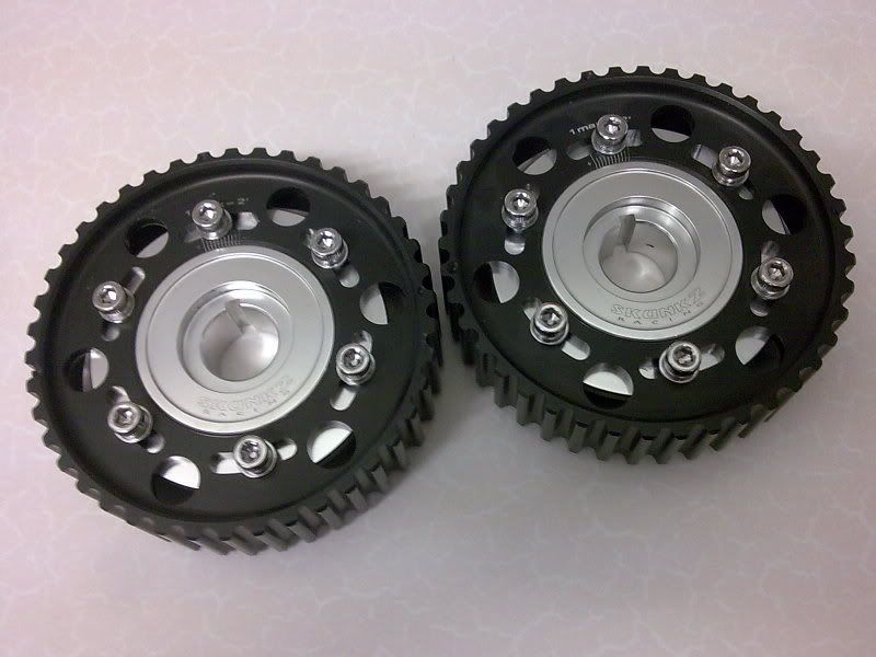
I've not got a proper picture of them fitted yet as I want to get a new rocker cover and cut away appropriately first :wink:

The "bargain" £150s worth of rubber and sheet metal I bought recently :lol: ...

Image

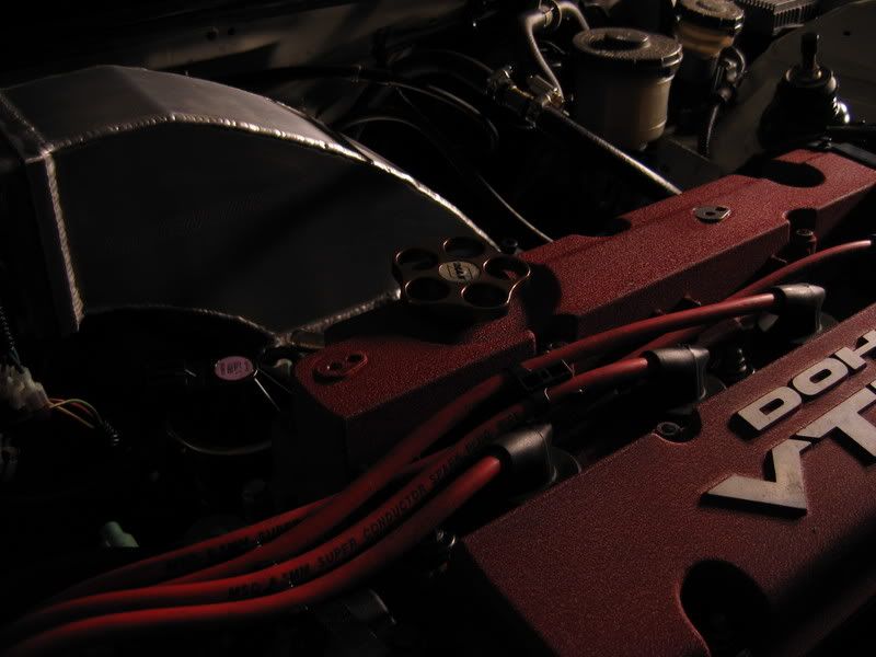
Then this arrived the other day, which was potentially the last part of my new induction set up...

Image

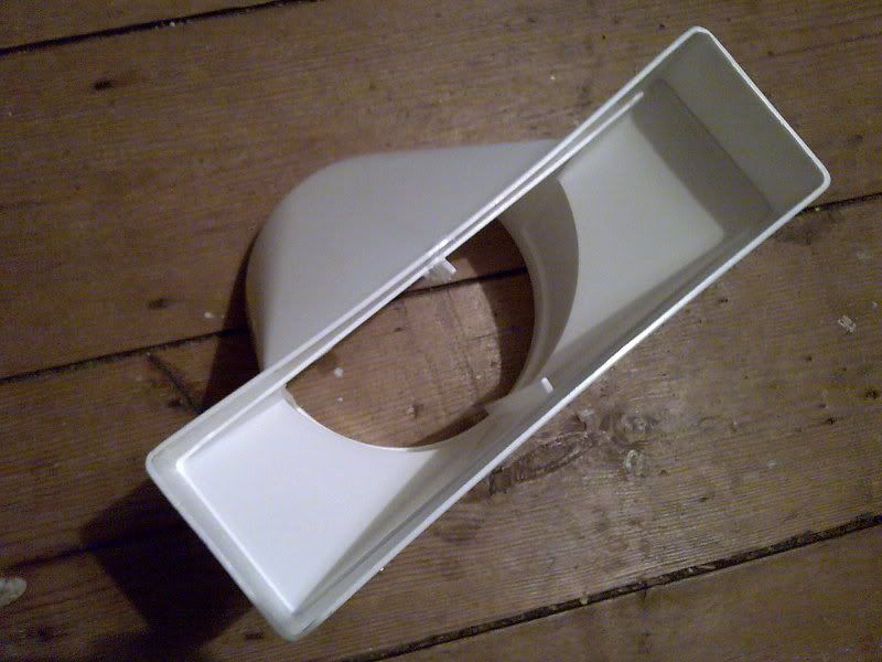
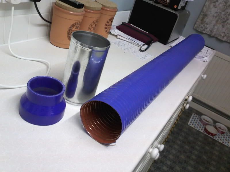
The plan was (being I need a new radiator), to go for a half-width radiator positioned central as possible, but allowing me to duct air from a straight line, from behind the bumper to where my filter currently sits (so basically the left side of OEM radiator) allowing as few bends as possible creating an efficient ram-air effect. In order to do this I've found the perfect "funnel"... from Tool Station 8) :lol: ...

Image

The rectangular intake is 204mm x 60mm and will fit perfectly in the upper grill of the front bumper. It then converts to a 5" diameter of which I will immediately adapt to 4" using this...

Image

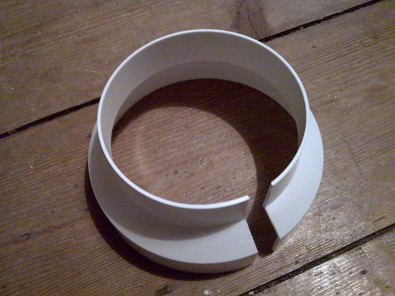
I had to cut a small section out in order to slot it in the "funnel". These two components will be painted black just so you know :wink:

Then when the time comes I shall use this lot to duct the air. It consists of a 102mm aluminum joiner, a 102mm-76mm Silicone reducer and a 1 metre length of 102mm diameter Silicone Ducting. I now actually have a potential means to having 102mm ends made up for my BMC-CDA filter to replace the standard 85mm ones to, but I'll get to that later :wink: ...

Image

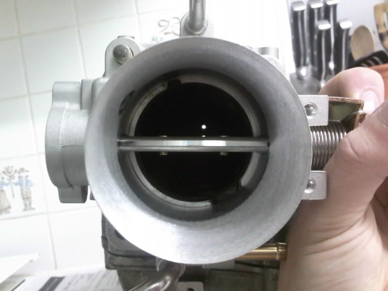
That lot will then connect to this bad boy :wink: ...

Image

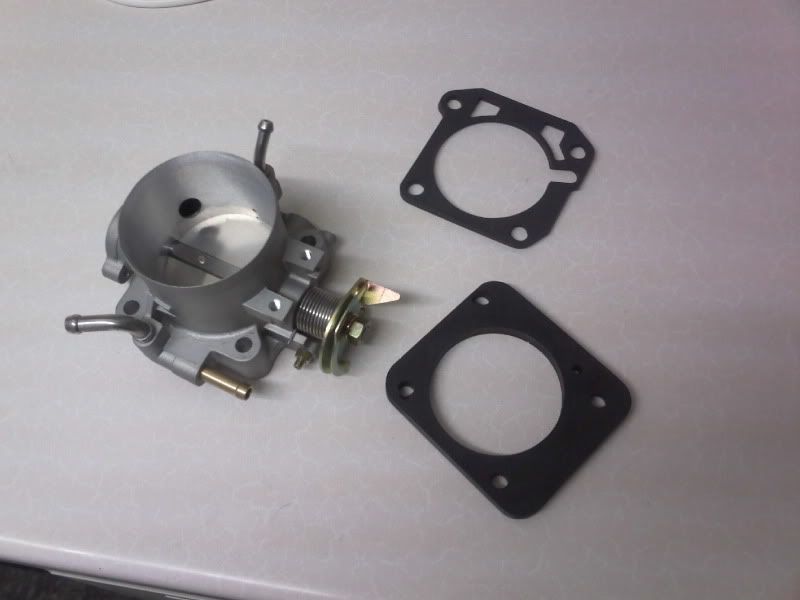
It's DH-Racing 74/68 throttle body I had shipped from the states.

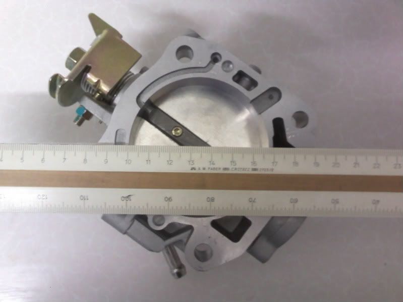
It kind of speaks for itself, in that it measures 74mm across the mouth...

Image

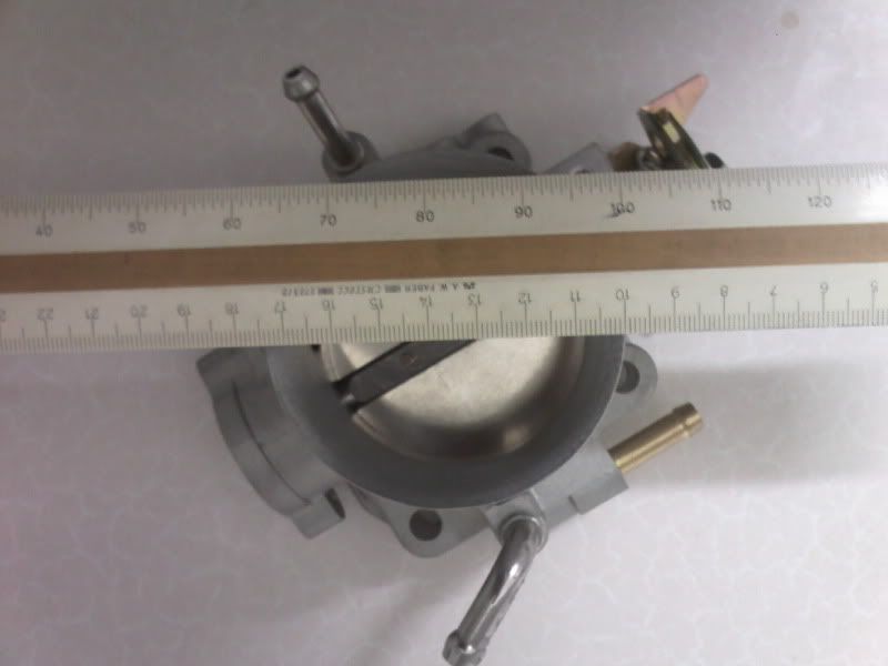
And tapers down to 68mm...

Image

The idea is obviously that I'm trying to get more air into the intake manifold, and by "Ramming" air in a 5 inch diameter at one end and gradually compressing it down to just under 2 3/4 inches, the force in which it enters is also going to be greater as well.

The reason I got a second the manifold is probably going to be quite obvious as well. I need to bore out the mouth in order to match the new throttle body...

Image

Fortunately for me I have a very good friend who is an EXCEPTIONAL machinist and willing to do the job for me :D

But not only that... I took the manifold over to show him on Saturday. He'd also invited his other machinist buddy over as well as we'd already been discussing a few potential projects :wink: 
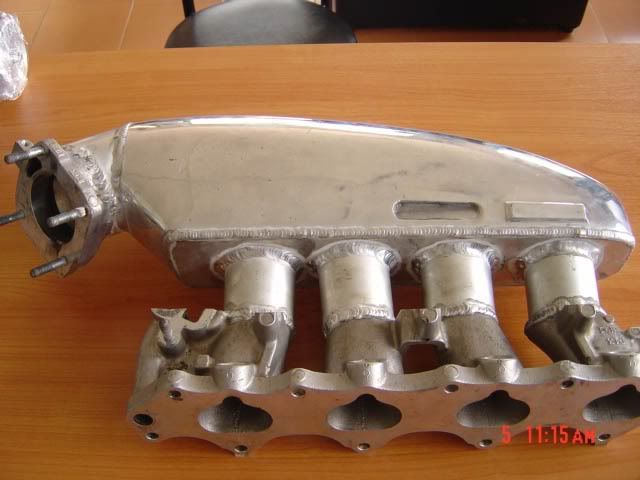
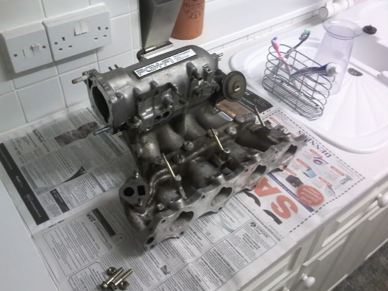
My initial intention was to do as some others have already done and polish the inside of the intake manifold. You can see here how poor the casting is...

Image

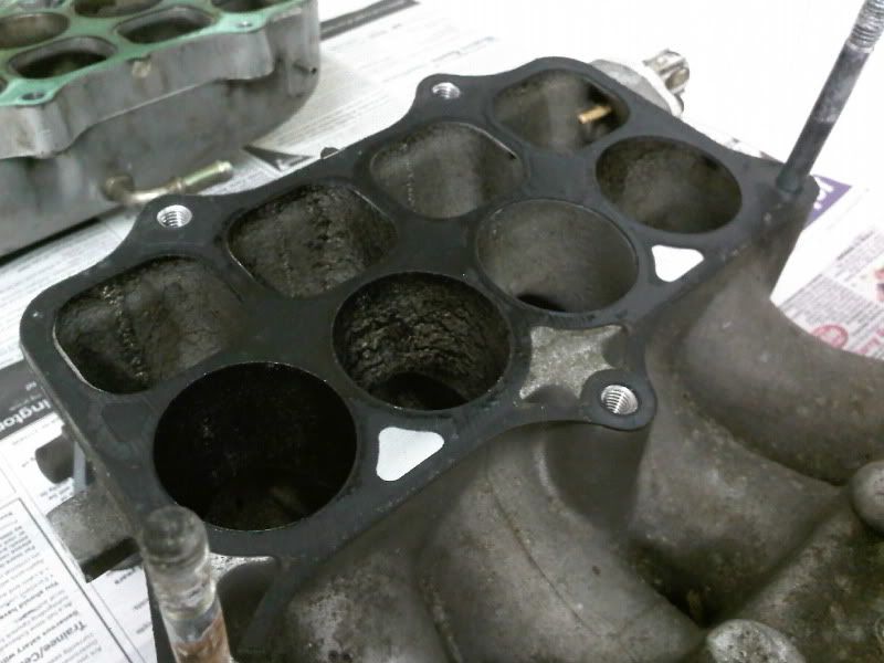
The black is obviously built up overtime, but it actually highlights exactly how rough the surface is :shock:

Anyway, you can also see how "lumpy-bumpy" the inside of the top portion of the intake is...

Image

Image

Ideally I'd like to fill-weld the recesses and then have everything polished allowing maximum air flow. In order to do this, the "webbing" of the top portion (The green in the next picture) would need to be cut away to give proper access. This would also mean some of the fixture points would need to be relocated. I would then be hoping to taper the webbing of the IABs to also help channel the air down. As many of you know the Skunk2 can cause a loss to lower end power due to the fact it has no IABs, so I have full intention to keep mine.

Image

Also, I intend to do away with the EGR valve. My buddy Dale could easily whip up a capping-off plate, but the internal exits which allow the exhaust gas back into the cold air passages are still going to cause a disruption to the air flow...

Image

Sooooooo... No sooner had I said my case... Without any hesitation whatsoever, both Dale and his pal "Vendi" (Apparently he has problems with vending machines :lol: ) Looked up from my napkin diagram and said... "Be easier to make one from scratch then?" :shock: ............ :D

So... looks like that's the plan now lads... My very own custom built intake manifold :D ... And what's going to be so great about it, is that Dale puts perfectionists to shame! :P He only feels something's worth doing if it out performs what's already out there (or be it at a lesser cost) and if he can make it look the dog's b*ll**ks 8) :lol:

Also, Dale and I had already talked about the manufacture of a few aftermarket trick bits to. Dale's in the process of furnishing a newly acquired workshop of which was intended for "hobby use" with the potential of making a little money on the side. Basically he's said that he wants to help transform my engine bay, and anything he makes for me (Being my car will be the guinea pig) will also be on offer for you guys to :D

I'll be putting a thread together for him nearer the time. So watch this space :wink:

And, back to the last couple of bits (Won't keep you much longer :wink: 
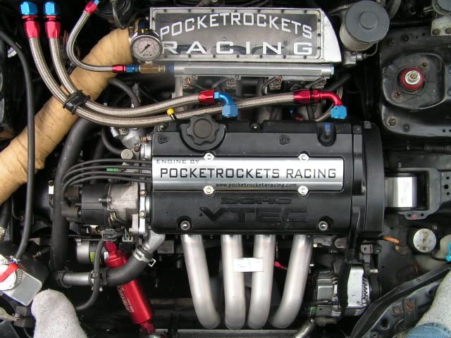
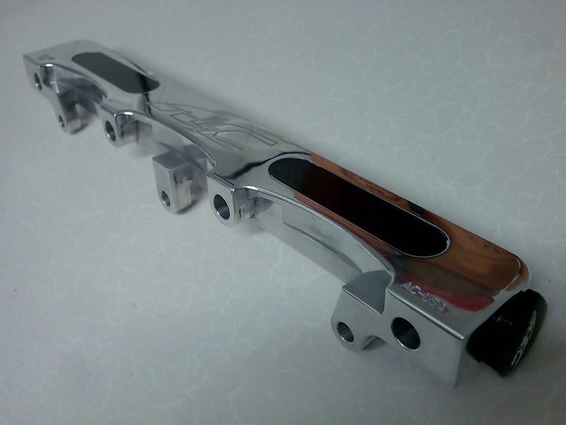
)... In ready and waiting I also have a nice and shiny AC Autotechnics 5/8" bore Fuel Rail, which will be accompanied by a power boost valve of some sort. I've not decided on whether to go FSE Power Boost valve, or a manually adjustable one of some sort yet...

Image

And an equally shiny catch tank to hopefully keep my new intake manifold clean :wink: ...

Image

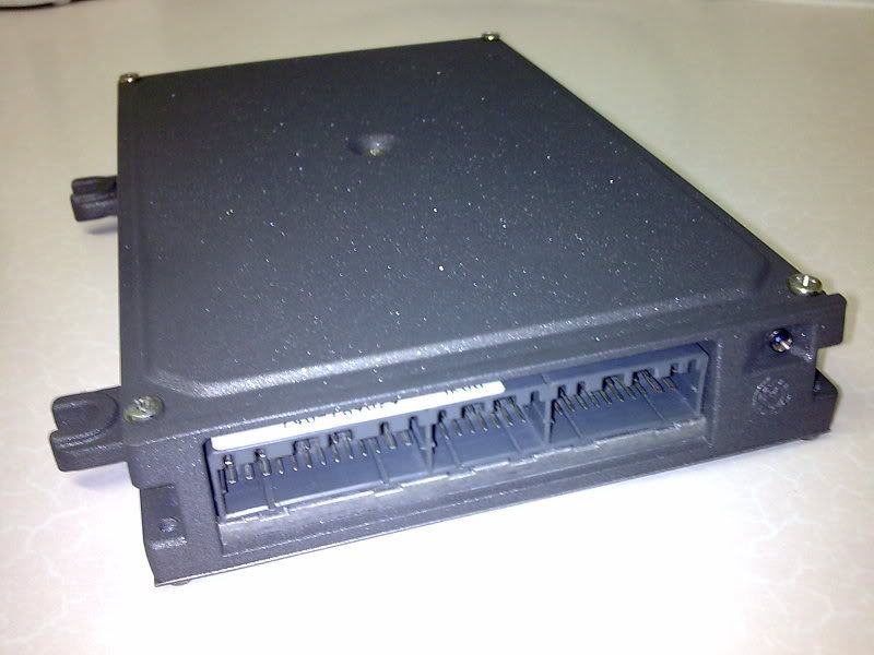
Then last, but far from least, to eventually tie everything together, as this would probably all be pointless without it... My sparkly, newly refurbished P28 ECU :wink: ...

Image

Image

There you go. And now back to work I go :)
Last edited by NafemanNathan on Tue Feb 07, 2012 2:06 pm, edited 1 time in total.

User avatar
NafemanNathan
LotM Winner
Posts: 20144
Joined: Sun Aug 08, 2010 9:37 pm
My Generation: 0G
Location: Yeovil, Somerset
Has thanked: 8 times
Been thanked: 124 times

Re: PLEASE DO NOT POST IN THIS THREAD YET (Under Constructio

Post by NafemanNathan » Tue Feb 07, 2012 9:28 am

handsomedanc wrote:good read mate glad to see your "issues" are behind you. looking forward to what your mate conjurs up for you
Ryan wrote:looks like things have taken a turn for the better then !
Junior Gee wrote:All this progress sounds good 8) I look forward to the updates. Sounds like the 'A' team are ready to perform. :lol: Hope it goes well for you dude :wink:
nucleustylz lude wrote: 8)

Ooh, more interesting bits indeed.

Be interesting what they come up with for an intake manifold, lucky little guinea pig indeed! :lol:

Oh and I like what you did with your P28 - never thought of giving it a lick of paint. Will be buying a spray can or two now! :D

Keep it up bud.
Crazy_C wrote:Oooooh, this is looking sweet man!! Sooo many shiney bits!! :D

Should get a quick removable **** so you can show off all the goodies when they're in there :D
Matt wrote:
Crazy_C wrote:Should get a quick removable **** so you can show off all the goodies when they're in there :D
for the last time Dom, in England we say BANANA HAMMOCK not a ****.
:lol: :lol: :lol:
Crazy_C wrote:
Matt wrote:
Crazy_C wrote:Should get a quick removable **** so you can show off all the goodies when they're in there :D
for the last time Dom, in England we say BANANA HAMMOCK not a ****.
:lol: :lol: :lol:
You want Nathan to have a quick removable banana hammock so he can show off all the goodies??? :shock: :shock: :shock: :shock:


Sorry for the whole **** / bonnet thing though, but y'all know what I mean :lol: :lol: When I remember, I'll write bonnet for y'all, keep you from moaning hahaaaa
Last edited by NafemanNathan on Tue Feb 07, 2012 1:09 pm, edited 2 times in total.

User avatar
NafemanNathan
LotM Winner
Posts: 20144
Joined: Sun Aug 08, 2010 9:37 pm
My Generation: 0G
Location: Yeovil, Somerset
Has thanked: 8 times
Been thanked: 124 times

Re: PLEASE DO NOT POST IN THIS THREAD YET (Under Constructio

Post by NafemanNathan » Tue Feb 07, 2012 9:28 am

Pick one :wink: ...

Image

I was actually toying with the idea of getting some bonnet rams as my prop's bracket finally gave up on me the other day. But they'll have to wait a while :wink:

Also, I may have given the wrong impression on this custom manifold project... It is "I" that has to do the main bulk of the designing and research :wink: I'll just have to keep reporting to Dale to make sure it's something he can actually manufacture. I've already done some brainstorming and things have already started looking a tad crazy :-s ....... :wink: 8)
Last edited by NafemanNathan on Tue Feb 07, 2012 1:10 pm, edited 2 times in total.

User avatar
NafemanNathan
LotM Winner
Posts: 20144
Joined: Sun Aug 08, 2010 9:37 pm
My Generation: 0G
Location: Yeovil, Somerset
Has thanked: 8 times
Been thanked: 124 times

Re: PLEASE DO NOT POST IN THIS THREAD YET (Under Constructio

Post by NafemanNathan » Tue Feb 07, 2012 9:29 am

Lude-Dude wrote:good luck, will be keeping a eye on this
nucleustylz lude wrote:Well here's a little inspiration:

Simplest :-

Image

Crazy :-

Image

Contraversal :-

Image
Image

:D
Last edited by NafemanNathan on Tue Feb 07, 2012 1:06 pm, edited 1 time in total.

User avatar
NafemanNathan
LotM Winner
Posts: 20144
Joined: Sun Aug 08, 2010 9:37 pm
My Generation: 0G
Location: Yeovil, Somerset
Has thanked: 8 times
Been thanked: 124 times

Re: PLEASE DO NOT POST IN THIS THREAD YET (Under Constructio

Post by NafemanNathan » Tue Feb 07, 2012 9:37 am

Crazy_C wrote:Unsurprisingly, I like the crazy one of the ITBs in the perspex box with the feed on them :mrgreen:

User avatar
NafemanNathan
LotM Winner
Posts: 20144
Joined: Sun Aug 08, 2010 9:37 pm
My Generation: 0G
Location: Yeovil, Somerset
Has thanked: 8 times
Been thanked: 124 times

(LB) Acoustic Supercharging

Post by NafemanNathan » Tue Feb 07, 2012 9:38 am

Shame it's not going to be filled with a coloured gas, else that window one would be fab! :lol:

Cheers for the inspiration Rob :D

There's actually only a handful of majorly varying designs of manifolds out there. Otherwise they're pretty much much of the same... And with the amount of research I've done I think I've now seen them all :lol:

And it's shocking to see just how many one-off "custom" manifolds have had no real thought put into them at all! They've literally just been fabricated to fit in a space and hold air :? This is normally the case with engine conversions where the new engine placement causes the standard intake manifold to foul on the bulkhead (or like). Many of them look to restrict air-flow over the original OEM intake manifold.

I've got several ideas already that I want to follow and the IABs part of the manifold is producing some interesting design ideas :wink: Once I've finished brainstorming and collated some designs together I'll post them up with the theories behind them.

There is obviously a science behind an intake manifold as well. The 3 attributes being Plenum volume, Runner length and Runner area.

There is another attribute, but this may be beyond my capabilities. It's refered to as "Acoustic Supercharging". I understand how it works, but I by no means have access to the correct equipment to test for it :(

This is a brief outlay of Acoustic Supercharging...

In a naturally aspirated engine, on the intake stroke, the piston
drops creating an area of low pressure in the combustion chamber that is less than atmospheric pressure and as the intake valve opens, the air from the outside is set in motion down the IM runner.

Once air (as a sound wave) has been set into motion down an IM runner, it does not simply stop when the intake valve is closed shut and wait for the intake valve to re-open. Instead, when the intake valve closes shut, this air sound wave bounces off the backface of the valve and travels at the speed of sound back up towards the IM plenum (rarefaction wave). This reflected wave has a frequency, amplitude, and negative pressure associated with it.

Once the wave reaches the plenum, the resonance wave is isolated and the plenum chamber behaves like a resonance chamber. The analogy used by most mechanical engineers to explain how a resonance chamber works is that it acts like an oscillating spring (i.e. imagine the plenum acts like the spring) with a block attached on the end of the spring (imagine the air wave in the IM runner to behave like the block). As the block compresses the spring, the spring builds or stores up energy and when the spring uncoils, the block is given a push or energy as it travels away from the spring's compressed position.

Like our block and spring, the air resonates (or compresses the spring) at a certain frequency (spring bouncing back and forth) inside the plenum and gains energy (pressure). The air wave is then bounced back at the speed of sound down the IM runner towards the intake valve again. But this time it has been given an extra "push" from the resonance chamber. The new sound wave going to the intake valve has a positive pressure and is travelling at a higher tone or energy (higher sound frequency).

The bouncing back and forth of sound waves from the closed intake valve to the plenum and then back down again occurs over several intake valve openings continuously. Why does this happen?

These reflected resonance waves don't reach the intake valve when it re-opens and therefore continue to reflect. This continues until several reflected air sound waves (or columns) stack up (amplified) at the closed intake valve. The energy (or pressure) of these amplified ( or stacked up ) reflected waves build up until they reach a maximum energy (and pressure).

The trick to resonance (or sound) tuning of the IM is to have these maximally amplified waves arrive at the intake valve just as it opens . The basic mechanism of intake manifold "tuning" or design is to provide high pressure at the intake valve so that the mass flow rate into the cylinder is boosted at a given engine speed or rpm. We do this "tuning" by changing the IM runner length and diameter (area).

By building up pressure from stacked resonating (or reflected) air sound waves (or columns) and releasing this "boost" at a specific rpm, you can get higher cylinder filling (i.e. achieve a volumetric efficiency (VE) greater than the cylinder swept volume. The engine breathes at a VE > 100%). The reflected positive pressure waves from the plenum, when it arrives at the right time, actually pushes in more air into the cylinder beyond the effects of the piston sucking in air. Not only do you control the location of where peak torque occurs by varying runner length and diameter, you get a gain in power by using the plenum's resonance effect. This is what we call " Acoustic Supercharging".


So the theory is simple :wink: :lol: ... But in practice... It is not :(

Besides, the whole IABs part of the H22a manifold would throw a whole toolbox of spanners in the works if designing with acoustic supercharging in mind... Though I do have an idea :wink:

Either way, I know that the shorter the runners, the higher the engine will rev. So I'm going to be working with that in mind to start with, but also take into account the comparison between the two different runner lengths of the OEM intake (The permanently open runners and the IAB runners).

That's all for now. Sorry this post has been all talk ( :-s ) but just thought I'd share some theories :)

Pictures soon :wink:
Last edited by NafemanNathan on Tue Feb 07, 2012 2:06 pm, edited 2 times in total.

User avatar
NafemanNathan
LotM Winner
Posts: 20144
Joined: Sun Aug 08, 2010 9:37 pm
My Generation: 0G
Location: Yeovil, Somerset
Has thanked: 8 times
Been thanked: 124 times

Re: PLEASE DO NOT POST IN THIS THREAD YET (Under Constructio

Post by NafemanNathan » Tue Feb 07, 2012 9:39 am

grafter wrote:oh man im in love lol
soooo jealous of you, i want all those goodies please
awesome write up man, keep it comming =D>

Post Reply

Return to “Lude Profiles”