
mercutio wrote:have you ever had a high spoiler they get on your nerves after a while
Congratulations to vtecmec for winning May/June's Lude Of The Month, with his DIY Turbo BB1 build.
>>> Click Here For Profile <<<

>>> Click Here For Profile <<<
Nathan's Road-Legal/Track BB4
-
NafemanNathan
- LotM Winner
- Posts: 20144
- Joined: Sun Aug 08, 2010 9:37 pm
- My Generation: 0G
- Location: Yeovil, Somerset
- Has thanked: 8 times
- Been thanked: 124 times
Re: PLEASE DO NOT POST IN THIS THREAD YET (Under Constructio

-
NafemanNathan
- LotM Winner
- Posts: 20144
- Joined: Sun Aug 08, 2010 9:37 pm
- My Generation: 0G
- Location: Yeovil, Somerset
- Has thanked: 8 times
- Been thanked: 124 times
Re: PLEASE DO NOT POST IN THIS THREAD YET (Under Constructio
Yeah, used to have a Valve Sports Type 2, much like your friend in your avatar again  lol
lol
-
NafemanNathan
- LotM Winner
- Posts: 20144
- Joined: Sun Aug 08, 2010 9:37 pm
- My Generation: 0G
- Location: Yeovil, Somerset
- Has thanked: 8 times
- Been thanked: 124 times
Re: PLEASE DO NOT POST IN THIS THREAD YET (Under Constructio
mercutio wrote:yeah i remember now i wanted that one lol
-
NafemanNathan
- LotM Winner
- Posts: 20144
- Joined: Sun Aug 08, 2010 9:37 pm
- My Generation: 0G
- Location: Yeovil, Somerset
- Has thanked: 8 times
- Been thanked: 124 times
(PUK) VSS/PAS Removal Mod
The next side project of many is the VSS assembly mod required for PS removal. I'm afraid I might just go a little Nucleustylz on you all now 
... Part 1:
As I'm sure some of you are aware, removing the PS and all of its pipework leaves you with two different sized hose connections sticking out just below the VSS (Vehicle Speed Sensor). There is little info about this mod on the net, so when Adam (CA121) kindly offered up a spare VSS assembly for the cost of postage, I thought I'd take one for the team to do a little investigation
Now please, if you feel anything I've said is wrong, please put me straight
The assembly minus the actual VSS...
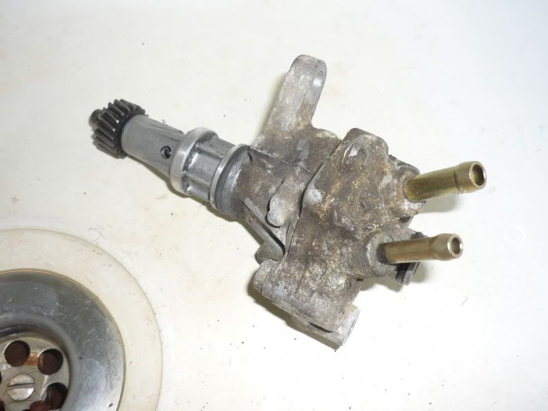
Now the questions were, do the two odd sized hose connections need to be looped, or simply capped? The logical theory having just removed part of the chain would be to loop them. Trouble is, being they are two subtly different ODs, finding a pipe to loop them with is impossible and boring out a smaller ID pipe on one end to suit the larger connector isn't ideal and is surprisingly difficult to get right. Also as the two connections run parallel with one another, a "U" shaped pipe is required, again limiting the options, or an annoyingly long piece of straight pipe is required in order to prevent any kinks. Thus looking naff.
The two odd sized hose connections in question...
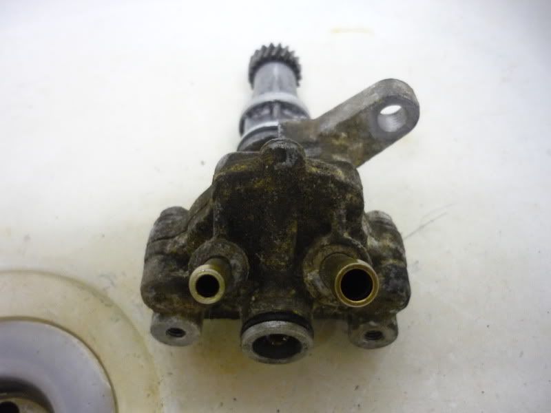
However! Having disassembled one of the VSS assemblies I can see that looping the pipes is not actually required
Underneath the cap of the assembly is a "wangle" style gearing which actually regulates the flow of oil to the steering rack...
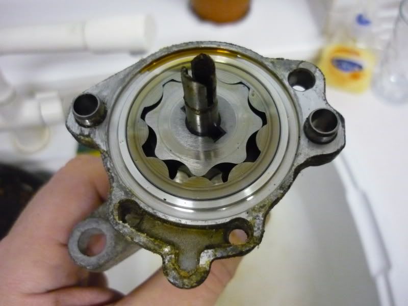
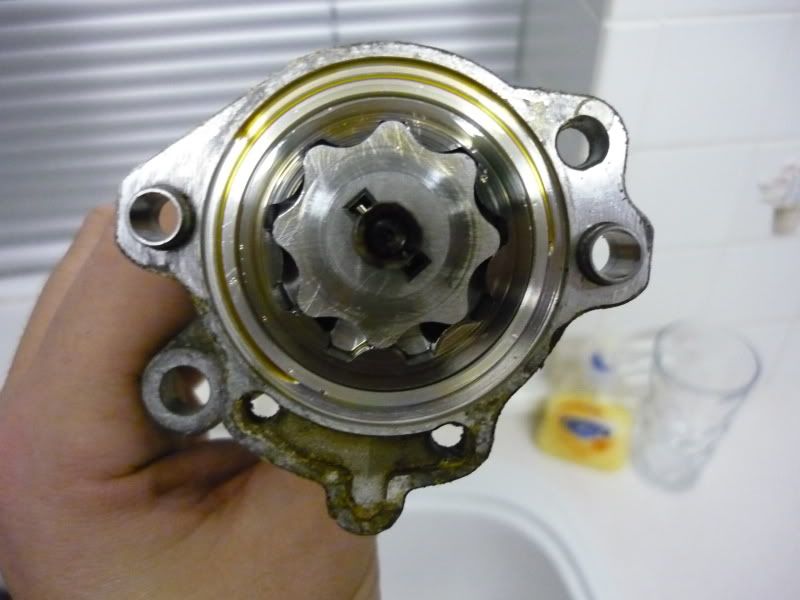
The faster the gearbox turns, the more oil is pumped through to the rack.
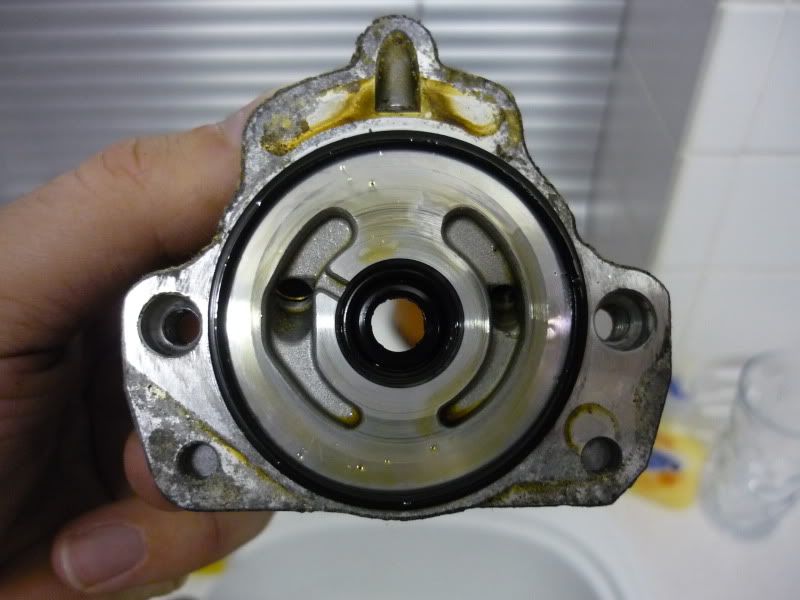
The cap...
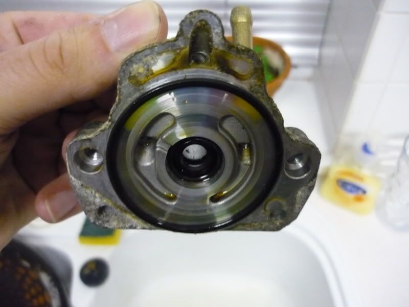
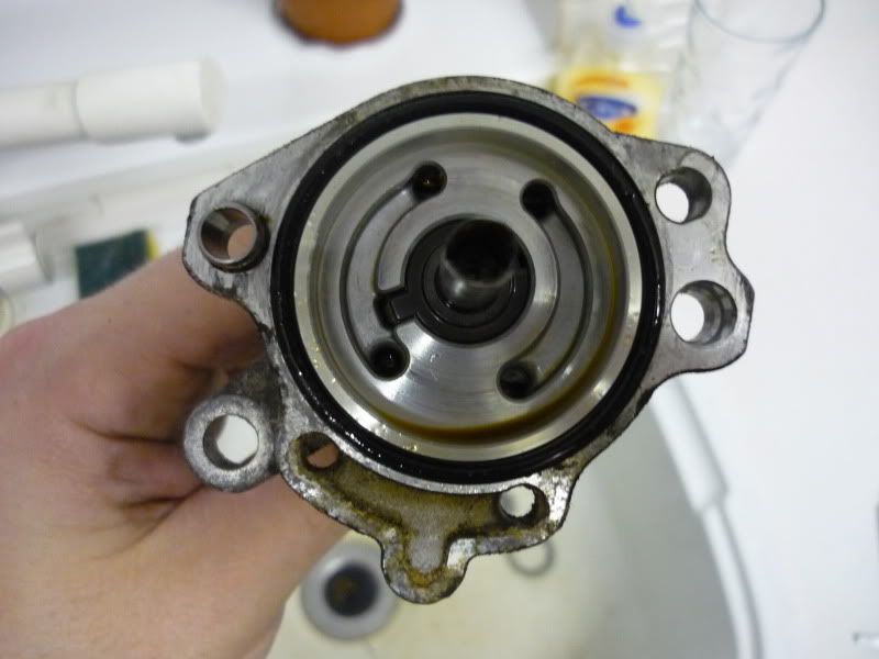
Now knowing the regulation side is no longer required, you can simply remove the "wangle" gearing. Which in turn allows the assembly to cycle the fluids within itself (Assuming the fluid is required to lube the centre shaft)...

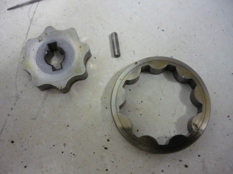
The only thing is from the "wangle" gear arrangement I have removed a key pin which not only held the internal gear in place, but also prevented the centre shaft (the bobbin) from dropping out. The thing I don't know yet, having not actually removed this from my car is whether this pin is still required, or whether the centre shaft is supported from within the gearbox. I can easily test this on a nice dry day
If the key pin is still required, I can simply re-install it with just the internal gear (possibly turned down if required).
The next step will be to re-cap the assembly back off. Either by means of using the existing cap, but with the hose connections removed and threads tapped to enable them to be capped off...
Or... make a new blanking cap that finishes it all off flush and remains inkeeping with my intake blanks It could easily be sealed using the existing centre shaft seal found in the OEM cap. Although it will still need to facilitate the actual VSS, so would be practically hidden and therefore likely to be a waste of time. Also the OEM cap looks to have a breathe hole/overflow in it. Again I don't know whether this is actually required now the PS has been removed. Shown here. It at the top of the picture and travels through to the centre bore...

Again, this could be easily replicated if I choose to make a blanking plate.
Either way I think this likely to be the best/easiest way to go about this mod. Only trouble is, I've not got a running car to test it on
So ... Phil?
... Part 1:
As I'm sure some of you are aware, removing the PS and all of its pipework leaves you with two different sized hose connections sticking out just below the VSS (Vehicle Speed Sensor). There is little info about this mod on the net, so when Adam (CA121) kindly offered up a spare VSS assembly for the cost of postage, I thought I'd take one for the team to do a little investigation
Now please, if you feel anything I've said is wrong, please put me straight
The assembly minus the actual VSS...
Now the questions were, do the two odd sized hose connections need to be looped, or simply capped? The logical theory having just removed part of the chain would be to loop them. Trouble is, being they are two subtly different ODs, finding a pipe to loop them with is impossible and boring out a smaller ID pipe on one end to suit the larger connector isn't ideal and is surprisingly difficult to get right. Also as the two connections run parallel with one another, a "U" shaped pipe is required, again limiting the options, or an annoyingly long piece of straight pipe is required in order to prevent any kinks. Thus looking naff.
The two odd sized hose connections in question...
However! Having disassembled one of the VSS assemblies I can see that looping the pipes is not actually required
Underneath the cap of the assembly is a "wangle" style gearing which actually regulates the flow of oil to the steering rack...
The faster the gearbox turns, the more oil is pumped through to the rack.
The cap...
Now knowing the regulation side is no longer required, you can simply remove the "wangle" gearing. Which in turn allows the assembly to cycle the fluids within itself (Assuming the fluid is required to lube the centre shaft)...
The only thing is from the "wangle" gear arrangement I have removed a key pin which not only held the internal gear in place, but also prevented the centre shaft (the bobbin) from dropping out. The thing I don't know yet, having not actually removed this from my car is whether this pin is still required, or whether the centre shaft is supported from within the gearbox. I can easily test this on a nice dry day
If the key pin is still required, I can simply re-install it with just the internal gear (possibly turned down if required).
The next step will be to re-cap the assembly back off. Either by means of using the existing cap, but with the hose connections removed and threads tapped to enable them to be capped off...
Or... make a new blanking cap that finishes it all off flush and remains inkeeping with my intake blanks
Again, this could be easily replicated if I choose to make a blanking plate.
Either way I think this likely to be the best/easiest way to go about this mod. Only trouble is, I've not got a running car to test it on
So ... Phil?
-
NafemanNathan
- LotM Winner
- Posts: 20144
- Joined: Sun Aug 08, 2010 9:37 pm
- My Generation: 0G
- Location: Yeovil, Somerset
- Has thanked: 8 times
- Been thanked: 124 times
Re: PLEASE DO NOT POST IN THIS THREAD YET (Under Constructio
jezer101 wrote:You have done all this and prepared to get a plate made up just because it looks abit messy
When will you be getting the car on the road!? As its for driving not to be sat on axle stands
-
NafemanNathan
- LotM Winner
- Posts: 20144
- Joined: Sun Aug 08, 2010 9:37 pm
- My Generation: 0G
- Location: Yeovil, Somerset
- Has thanked: 8 times
- Been thanked: 124 times
Re: PLEASE DO NOT POST IN THIS THREAD YET (Under Constructio
You say "all this", but it literally took me 5 minutes to take it apart last night and examine it. Took me longer to write all that gumph above!jezer101 wrote:You have done all this and prepared to get a plate made up just because it looks abit messy
When will you be getting the car on the road!? As its for driving not to be sat on axle stands
Pretty much everything in my engine bay is on display and I like attention to detail, what can I say?
And due to my certain circumstances I'm literally just finding lude related things that I can do in the house and be able to put down at the drop of a hat
-
NafemanNathan
- LotM Winner
- Posts: 20144
- Joined: Sun Aug 08, 2010 9:37 pm
- My Generation: 0G
- Location: Yeovil, Somerset
- Has thanked: 8 times
- Been thanked: 124 times
Re: PLEASE DO NOT POST IN THIS THREAD YET (Under Constructio
4thgenphil wrote:ha, you said running car
my head hurts. will read again tomorrow
-
NafemanNathan
- LotM Winner
- Posts: 20144
- Joined: Sun Aug 08, 2010 9:37 pm
- My Generation: 0G
- Location: Yeovil, Somerset
- Has thanked: 8 times
- Been thanked: 124 times
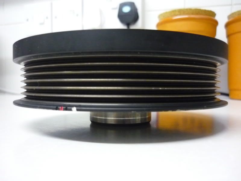
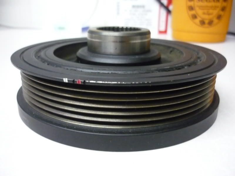
(PUK) New Fidanza Flywheel & S2000 Crank Pulley
Yet more bits to add to the... pile 
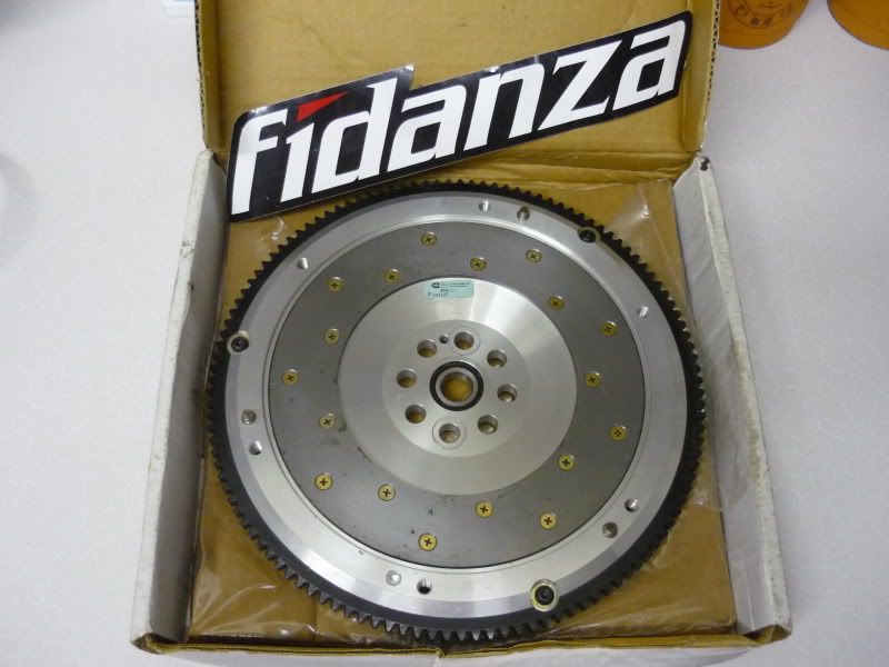
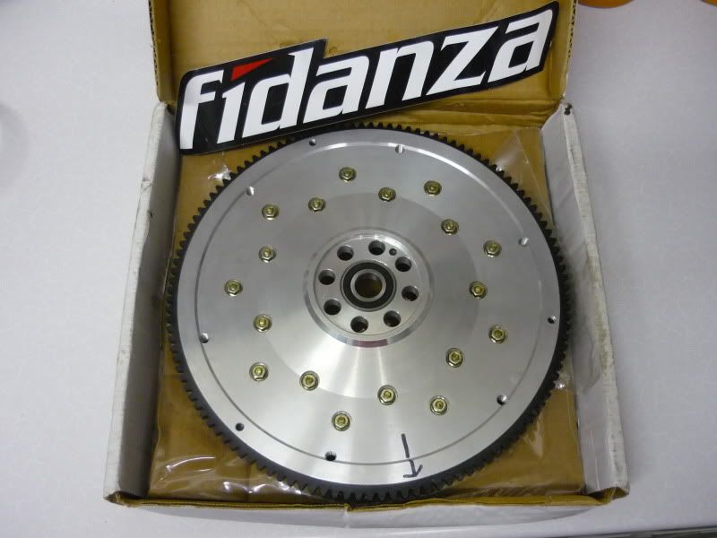
Bargain fitted, but never used Fidanza 3.6kg Flywheel...
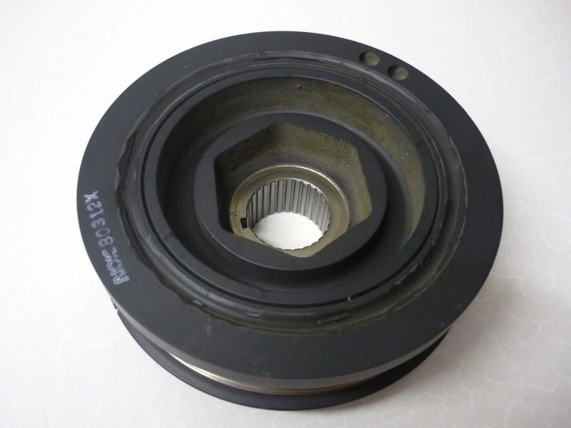
Bargain mint condition S2000 Crank Pulley, which will work as an underdrive pulley as it's that much smaller and a bit lighter than the Prelude pulley and will work in collaboration with my High-Output D-series Alternator.
[EDIT] Neither of which are a straight forward swap by the way.
Current standing (quite literally) parts list is on page 1.
Bargain fitted, but never used Fidanza 3.6kg Flywheel...
Bargain
[EDIT] Neither of which are a straight forward swap by the way.
Current standing (quite literally) parts list is on page 1.
-
NafemanNathan
- LotM Winner
- Posts: 20144
- Joined: Sun Aug 08, 2010 9:37 pm
- My Generation: 0G
- Location: Yeovil, Somerset
- Has thanked: 8 times
- Been thanked: 124 times
Re: PLEASE DO NOT POST IN THIS THREAD YET (Under Constructio
Merlin wrote:Where did you find out about the S2k pulley? What evidence is there that it will work? What size is it compared to other underdrive pulleys so what belt size would you need? It is 6 groove yeah?
I am interested :-k
Dino wrote:Coming along nicely nathan.
More bits. Hell of a spec list on page 1! !!!
Really looking forward to seeing the finished product.
Whos doing port work on your head?
-
NafemanNathan
- LotM Winner
- Posts: 20144
- Joined: Sun Aug 08, 2010 9:37 pm
- My Generation: 0G
- Location: Yeovil, Somerset
- Has thanked: 8 times
- Been thanked: 124 times
Re: PLEASE DO NOT POST IN THIS THREAD YET (Under Constructio
Came across it searching for a hard to find Euro-R pulley and realised it was something I wanted to give a go. I've only seen the one guy from the States that managed it, and he apparently got the idea from only one other guy, so not been attempted that muchMerlin wrote:Where did you find out about the S2k pulley? What evidence is there that it will work? What size is it compared to other underdrive pulleys so what belt size would you need? It is 6 groove yeah?
I am interested :-k
So there's that guy that got it to work, but I don't see why it wouldn't work anyway. Not sure how it compares to other underdrive pullies, but being OEM it's obviously a quality part and I intend to get the full cranking assembly re-balanced anyway. The pulley would need spacing out to line up with the OEM alternator, but being I'm planning on running a D-Series alternator in a different location I need to custom fabricate a new mount anyway, so can play with all of that. Which also means the length of the belt can vary as well.
It is 6 groove yeah, but the alternator pulley is only 4, so I might go with a 4 PUK belt. Not sure yet