
Congratulations to vtecmec for winning May/June's Lude Of The Month, with his DIY Turbo BB1 build.
>>> Click Here For Profile <<<

>>> Click Here For Profile <<<
Supercharged Mugen Lude (03/06/14 Update!)
-
NafemanNathan
- LotM Winner
- Posts: 20144
- Joined: Sun Aug 08, 2010 9:37 pm
- My Generation: 0G
- Location: Yeovil, Somerset
- Has thanked: 8 times
- Been thanked: 124 times


-
nucleustylzlude

- Moderator
- Posts: 4013
- Joined: Wed Aug 11, 2010 11:46 pm
- My Generation: 4G
- Location: Bristol, UK!
- Been thanked: 7 times
- Contact:
 BUILD PART 4) - Parts (Cont'd) – More Cooling
BUILD PART 4) - Parts (Cont'd) – More Cooling
Additive Cooling!
I ran through various additions and upgrades on the cooling side of things, mostly consisting of a larger capacity aluminium rad, some stronger rad hoses and what not. In addition to the Rad and hoses, during the new water/antifreeze mix that will be going into the car I will by trying out some of this stuff:
http://www.opieoils.co.uk/p-60238-mille ... ancer.aspx
Super Duper Cooling!
Next up I have now decided to cool the intake air with the aid of some Water Injection!
A lot of guys in the states running a JRSC and have upgraded from 6psi to 9psi have added water injection as a safe way of cooling the charged intake air. With the location of the Eaton roots type supercharger sitting directly to the lower intake manifold there is little room, if at all to run an intercooler of any type. I’m still certain it can be done, but it means a lot of custom work and more £££. So this being a proven easy to add option looked the way to go for some longevity.
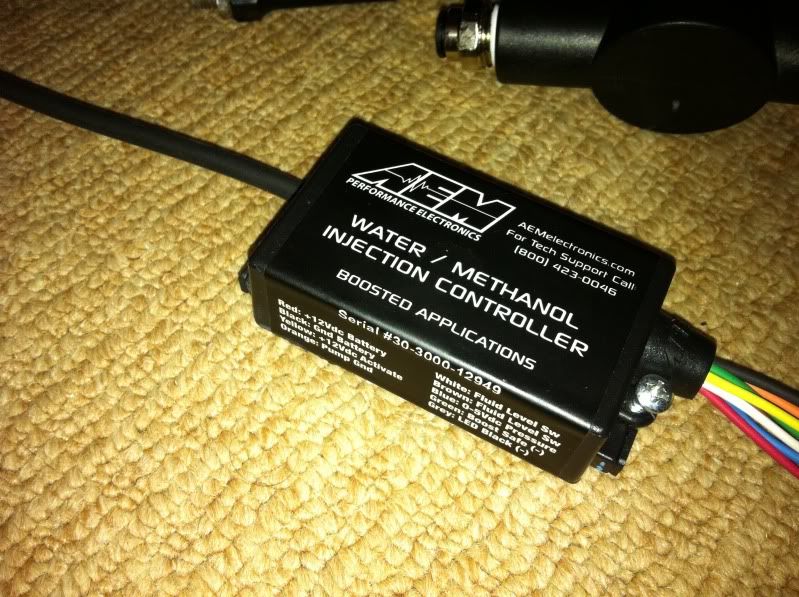
I hunted around for a while for a decent second hand kit, and was outbid on numerous auctions. Finally I got a second chance offer on an AEM kit. One of the preferred kits as it has some nice electronic management with it. Here’s some info from AEM’s site:

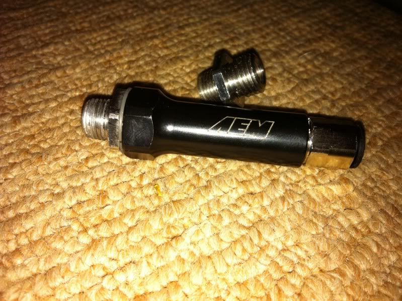
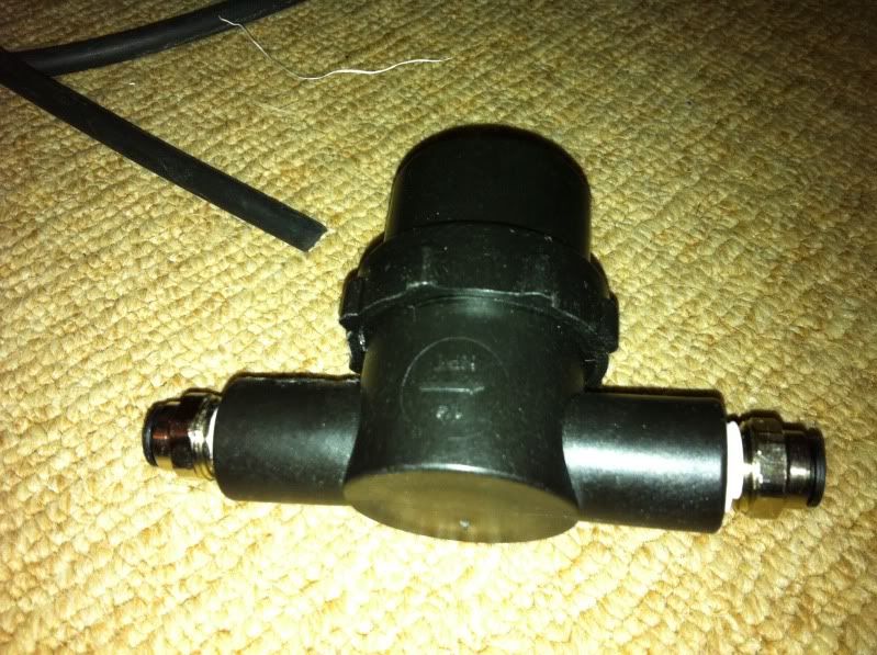
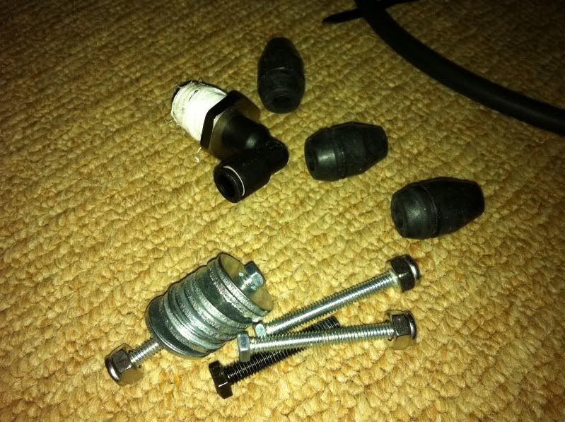
Here is the kit I received. It was everything but a tank from the basic kit – High pressure water pump & fixings, AEM electronics progressive module, check valve, jets, bulkhead grommets, additional push fit fittings, tank tap fitting and an array of hoses. But it also had an additional item – a filter unit (another £25 from AEM!) which was unexpected:

I wasn’t too bothered about no tank as I wanted something larger than their 1 gallon (about 5 litres) and something custom. As a result of no tank, there was also no float switch – I.e. nothing to wire up to the electrics to let me know when the fluid is running low. So what to do for the missing parts?
First thing was to source a tank which I would want to mount it in the boot (trunk to you foreigners). I looked at several very expensive fabricated items directly for water injection at £85-200! Expensive stuff! Then looked into plastic storage containers, a lot cheaper, but not quite the ‘look’ I’d want visible in a stripped out car. Then while cruising around a car boot I saw an item which gave me a brain wave - Use a nice metal jerry can!
An ebay search later and £19.99 of your finest UK pounds and I had this delivered:
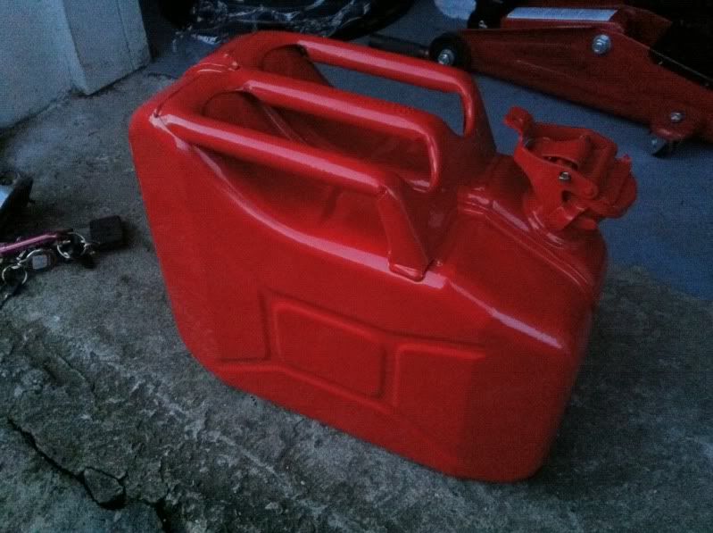
I went for a red can with a 10 litre capacity – looked a good shape too rather than the tall ones to make the mounting easier.
Next up was a way of securing it. I’ve picked up a couple of options, depending on which is the most secure. I have some small red ratchet straps:
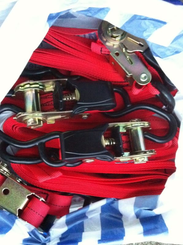
OR…
Some red karabiner bungee lines I have – no pics at the mo.
The bungees would be easier to fit I think, we’ll see.
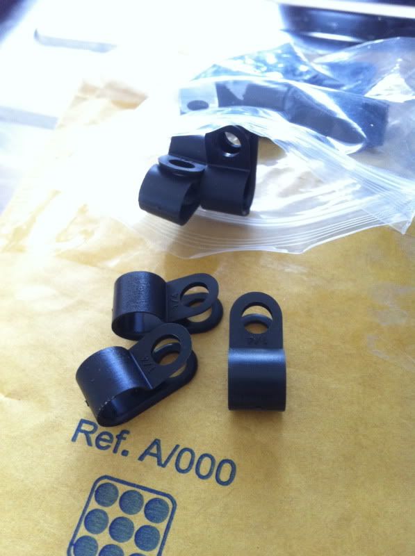
Next up was some more high pressure nylon hose as the kit doesn’t have enough for the boot mounting. This stuff is a lot cheaper than I thought – 4mm inner diameter and 6mm outer in red:
http://www.ebay.co.uk/itm/Nylon-Pneumat ... 5f7a054535
Then some nylon P clips to route them through the car to the engine bay – again cheap as chips!
Final thing for the system was a float switch to utilise the AEM’s failsafe LED code when I run low on water/meth mixture. About £7-8 from the same place most of our electrical stuff is from – China:
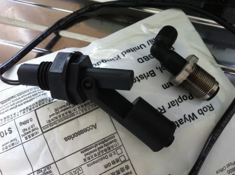
Plus I made sure to find one where I can secure it from the outside in order to fit on the jerry can.
I plan to install the jet/check valve into the intake piping before the throttle body. This isn’t the most ideal situation as there are rumours from Jackson Racing themselves that water injection (especially with methanol mixture) can strip the superchargers rotors of their Teflon coating over time. But I’ve yet to see a before and after use where they don’t look exactly the same! Just sounds like @ss covering responses to me. A direct port system to each of the 4 runners would be a more efficient setup, or even better combined with the pre-TB injection. This is mainly because a lot of the cooling effect will be used on cooling the supercharger and rotors, which in turn will reduce the overall operating temps and thus intake charge temps. But this obviously has the effect of reducing the conditions within the combustion chamber.
Overall though, pre-TB is easiest and still yields gains that has seen many a JRSC 9psi Prelude see many miles and are still going. So tried and tested I’ll lay my hat on.
I think that’s it from the cooling side. Maybe worth noting that the thicker core rad I will be installing has made the chunky fan redundant in terms of the front engine mount. So one or two slimline fans are now on the cards – looking at either Mishimoto which appear to be a rebranded item or finding a couple of used Spal fans from the likes of Elises and VX220’s.
Cheers again if anyone reads my ramblings!
Rob
Additive Cooling!
I ran through various additions and upgrades on the cooling side of things, mostly consisting of a larger capacity aluminium rad, some stronger rad hoses and what not. In addition to the Rad and hoses, during the new water/antifreeze mix that will be going into the car I will by trying out some of this stuff:
http://www.opieoils.co.uk/p-60238-mille ... ancer.aspx
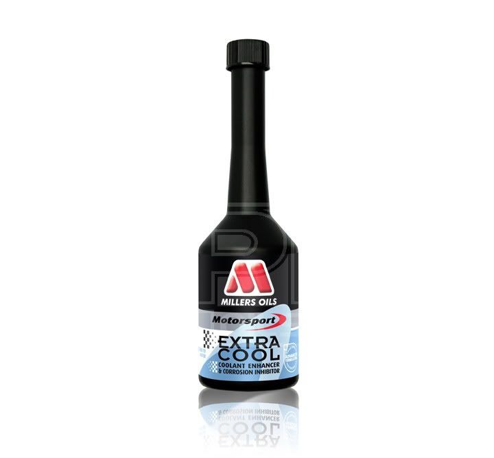
Worth a try, anything to help cooling by 15 degrees is worth a shot.About Millers Oils Extra Cool corrosion inhibitor and coolant enhancer
Concentrate multi-metal corrosion inhibitor and coolant enhancer. Dilute with water in the ratio 1 part Extra Cool to 50 parts water [2% solution] for corrosion inhibition of vehicle cooling systems and deposit reduction.
Benefits of Millers Oils Extra Cool corrosion inhibitor and coolant enhancer
• Helps to maintain coolant flow in radiators.
• Reduces deposit formation in radiators.
• Provides powerful corrosion protection for all metals found in engines e.g. aluminium, cast iron, etc.
• Helps reduce coolant temperature by up to 15 degrees.
PERFORMANCE PROFILE
• Reduces engine damage from internal coolant leaks.
• Mixes with all good quality antifreezes.
• Does not provide antifreeze protection.
Super Duper Cooling!
Next up I have now decided to cool the intake air with the aid of some Water Injection!
A lot of guys in the states running a JRSC and have upgraded from 6psi to 9psi have added water injection as a safe way of cooling the charged intake air. With the location of the Eaton roots type supercharger sitting directly to the lower intake manifold there is little room, if at all to run an intercooler of any type. I’m still certain it can be done, but it means a lot of custom work and more £££. So this being a proven easy to add option looked the way to go for some longevity.
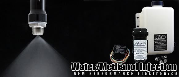
I hunted around for a while for a decent second hand kit, and was outbid on numerous auctions. Finally I got a second chance offer on an AEM kit. One of the preferred kits as it has some nice electronic management with it. Here’s some info from AEM’s site:
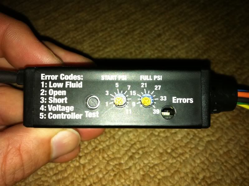
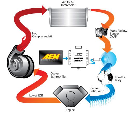
Looks good, obviously the pic of the turbo setup is different to mine but the principles are the same. The main thing for me was the progressive injection for set psi’s, the failsafe errors and that it was compatible with water AND methanol (50% max).AEM wrote: Overview
The AEM Water/Methanol Injection kit with 1 gallon tank includes all the elements necessary to do water/methanol injection right on nearly every forced induction gasoline vehicle. Imagine having the benefits of a super efficient intercooler and race gas-like detonation control but for hundreds of dollars less and all packaged in a complete kit. Run more boost and ignition timing to gain as much as 20% more horsepower while still using pump gas!
Key Features
Comes loaded with more standard high quality features and functionality than any other comparably priced system available, including:
· 1 Gallon tank with built in low level switch
· Boost referenced progressive controller
· “Boost Safe” readiness safety system
· One machined billet injector with integral check valve to prevent unintended flow
· Three interchangeable injector nozzles to cover a wide range of HP levels
· Recirculation-style pump with integral fittings
· LED dash light for system status and low fluid warning
· 20 ft. of injection tubing
How Water/Methanol Injection Works
Reduce Inlet Air Charge Temperatures
Water/methanol injection helps to reduce inlet air charge temperatures and suppress detonation. A highly atomized mist of water/methanol mix is injected into the inlet airstream where it immediately starts to evaporate. The air charge temperature is reduced through evaporative cooling as the fluid changes states and goes from a liquid to a vapor. This “liquid intercooling” effect can reduce intake air temperatures by as much as 100°F or more! A cooler, denser air charge delivers more oxygen that allows for more fuel to be burned and more horsepower to be made. A cooler air charge also helps increase the knock threshold by reducing the chance of pre-ignition and detonation.
Reduce Knock
Combined, water and methanol can significantly increase your effective anti-knock index allowing for higher boost pressures and more ignition timing advance. Water absorbs heat which allows it to reduce excessive combustion temperatures and slow down the combustion rate. By slowing and controlling the combustion rate the chance of detonation occurring is greatly reduced. Methanol is a cool burning, high anti-knock rated fuel that also helps to cool and control combustion.
Reduce Carbon Deposits
Water/methanol injection will reduces carbon deposits inside the combustion chamber and in the intake manifold. Many engines use Exhaust Gas Recirculation (EGR) for emissions control which can lead to massive carbon build up inside the air intake. Water/methanol injection will help to eliminate this build up and promote better airflow for better engine efficiency. Reducing carbon build up in the combustion chamber helps to reduce “hot spots” that can cause unwanted pre-ignition and detonation. In some instances, water/methanol injection can also slightly increase fuel economy.
Luvly Jubbly!
Boost Referenced Progressive Controller
The AEM Water/Methanol Injection System uses an on-demand boost referenced progressive controller to drive a high pressure injection pump. Basing injection progressively on manifold pressure allows for the correct amount of water/methanol to be injected at all points along the engine’s power curve. At lower boost levels where only a small amount of water/methanol flow is needed, the controller drives the pump at low speed delivering the necessary flow rate. As boost increases, along with intake air temperatures increasing as well, the controller increases the pump speed allowing for more water/methanol to be injected into the engine, helping to cool and control combustion when it’s needed most.
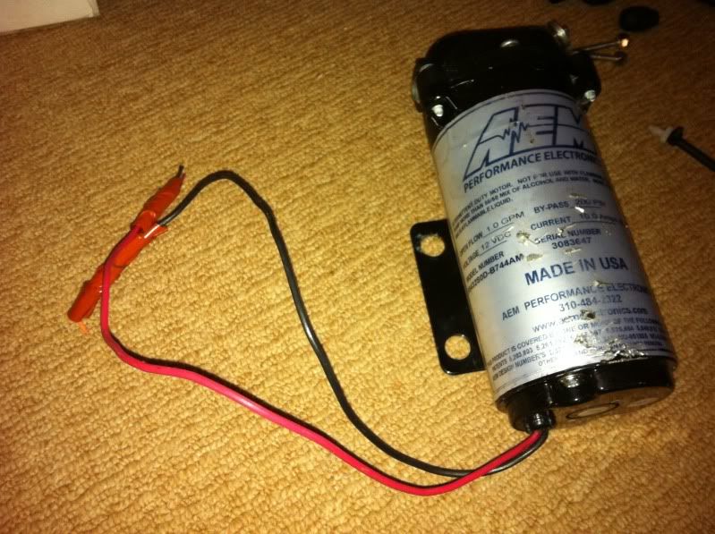
Here is the kit I received. It was everything but a tank from the basic kit – High pressure water pump & fixings, AEM electronics progressive module, check valve, jets, bulkhead grommets, additional push fit fittings, tank tap fitting and an array of hoses. But it also had an additional item – a filter unit (another £25 from AEM!) which was unexpected:
I wasn’t too bothered about no tank as I wanted something larger than their 1 gallon (about 5 litres) and something custom. As a result of no tank, there was also no float switch – I.e. nothing to wire up to the electrics to let me know when the fluid is running low. So what to do for the missing parts?
First thing was to source a tank which I would want to mount it in the boot (trunk to you foreigners). I looked at several very expensive fabricated items directly for water injection at £85-200! Expensive stuff! Then looked into plastic storage containers, a lot cheaper, but not quite the ‘look’ I’d want visible in a stripped out car. Then while cruising around a car boot I saw an item which gave me a brain wave - Use a nice metal jerry can!
An ebay search later and £19.99 of your finest UK pounds and I had this delivered:
I went for a red can with a 10 litre capacity – looked a good shape too rather than the tall ones to make the mounting easier.
Next up was a way of securing it. I’ve picked up a couple of options, depending on which is the most secure. I have some small red ratchet straps:
OR…
Some red karabiner bungee lines I have – no pics at the mo.
The bungees would be easier to fit I think, we’ll see.
Next up was some more high pressure nylon hose as the kit doesn’t have enough for the boot mounting. This stuff is a lot cheaper than I thought – 4mm inner diameter and 6mm outer in red:
http://www.ebay.co.uk/itm/Nylon-Pneumat ... 5f7a054535
Then some nylon P clips to route them through the car to the engine bay – again cheap as chips!
Final thing for the system was a float switch to utilise the AEM’s failsafe LED code when I run low on water/meth mixture. About £7-8 from the same place most of our electrical stuff is from – China:
Plus I made sure to find one where I can secure it from the outside in order to fit on the jerry can.
I plan to install the jet/check valve into the intake piping before the throttle body. This isn’t the most ideal situation as there are rumours from Jackson Racing themselves that water injection (especially with methanol mixture) can strip the superchargers rotors of their Teflon coating over time. But I’ve yet to see a before and after use where they don’t look exactly the same! Just sounds like @ss covering responses to me. A direct port system to each of the 4 runners would be a more efficient setup, or even better combined with the pre-TB injection. This is mainly because a lot of the cooling effect will be used on cooling the supercharger and rotors, which in turn will reduce the overall operating temps and thus intake charge temps. But this obviously has the effect of reducing the conditions within the combustion chamber.
Overall though, pre-TB is easiest and still yields gains that has seen many a JRSC 9psi Prelude see many miles and are still going. So tried and tested I’ll lay my hat on.
I think that’s it from the cooling side. Maybe worth noting that the thicker core rad I will be installing has made the chunky fan redundant in terms of the front engine mount. So one or two slimline fans are now on the cards – looking at either Mishimoto which appear to be a rebranded item or finding a couple of used Spal fans from the likes of Elises and VX220’s.
Cheers again if anyone reads my ramblings!
Rob

-
NafemanNathan
- LotM Winner
- Posts: 20144
- Joined: Sun Aug 08, 2010 9:37 pm
- My Generation: 0G
- Location: Yeovil, Somerset
- Has thanked: 8 times
- Been thanked: 124 times
-
nucleustylzlude
- Moderator
- Posts: 4013
- Joined: Wed Aug 11, 2010 11:46 pm
- My Generation: 4G
- Location: Bristol, UK!
- Been thanked: 7 times
- Contact:
Re: Supercharged Mugen Lude
Yeah it was a little late Friday night post wasn't it!
More to come - I will post some progress of the actual car soon, honestly!
-
mercutio

- LotM Winner
- Posts: 14958
- Joined: Sun Aug 08, 2010 8:45 pm
- My Generation: 5G
- Location: Sunny Manchester
- Has thanked: 1 time
- Been thanked: 4 times
- Contact:
great work rob i admire your research matey you cover all bases
bristol_bb4 wrote:ahhh a 5th gen, i love 5th gens
Dino wrote:I loves the 5th gen really.... just dont quote me on it...
4thgenphil wrote:Mines 4 1/4 unches mate, sorry
http://www.ludegeneration.co.uk/profile ... -t618.html
-
nucleustylzlude
- Moderator
- Posts: 4013
- Joined: Wed Aug 11, 2010 11:46 pm
- My Generation: 4G
- Location: Bristol, UK!
- Been thanked: 7 times
- Contact:
BUILD PART 4) - Parts (Cont'd) – Intake & Exhaust
BUILD PART 4) - Parts (Cont'd) – Intake & Exhaust
Intake & Exhuast
Intake system
Well, as with a lot of things in my build, this wasn’t in my initial plans but as time goes on and parts crop up I find myself buying more and more to make the build a little more interesting!
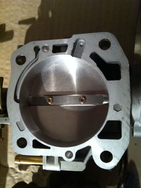
First up I had discounted a larger throttle body (TB), mainly because of the expense and secondly because of the limits of the size of the TB to the JRSC kits cast inlet pipe. I hadn’t looked into it much in the early days, but now with the kit in hand and measurements taken, it looked to be that 68mm would be the safe limit to go without having to add some welding material into an open port of the inlet pipe. So I looked for a budget aftermarket TB, I wasn’t concerned with the big bucks CNC items from Skunk2, plus I’ve heard of them sticking more so than cast items. So fell upon this one, which a couple of guys have used and rated now – a CNT 68mm cast TB which comes with a 68mm matched gasket and a brand new TPS (throttle position sensor) & gasket too – a bonus! Here’s some pics:
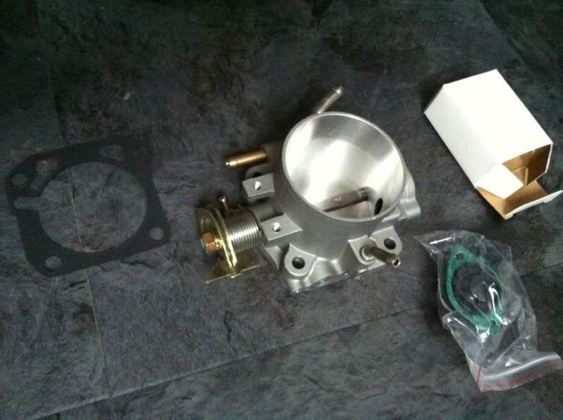

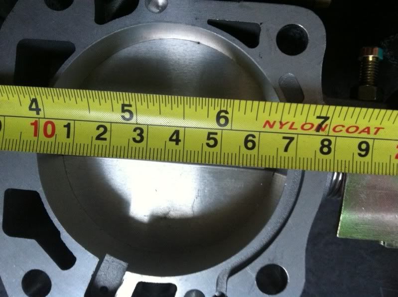
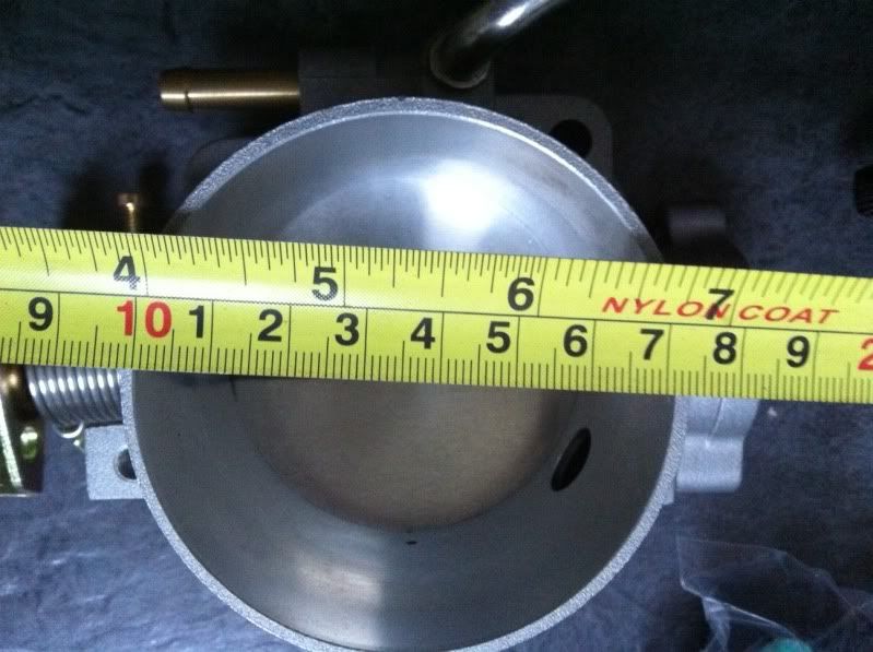
As you can see the engine side is 68mm, but the opening to the intake tubing tapers out to around 71.5mm. Should add some minor improvement to the setup and give some improved throttle response.
Here is how it compares with the OEM throttle body:
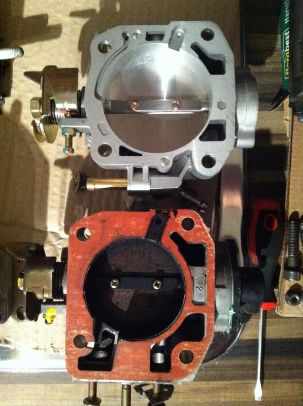
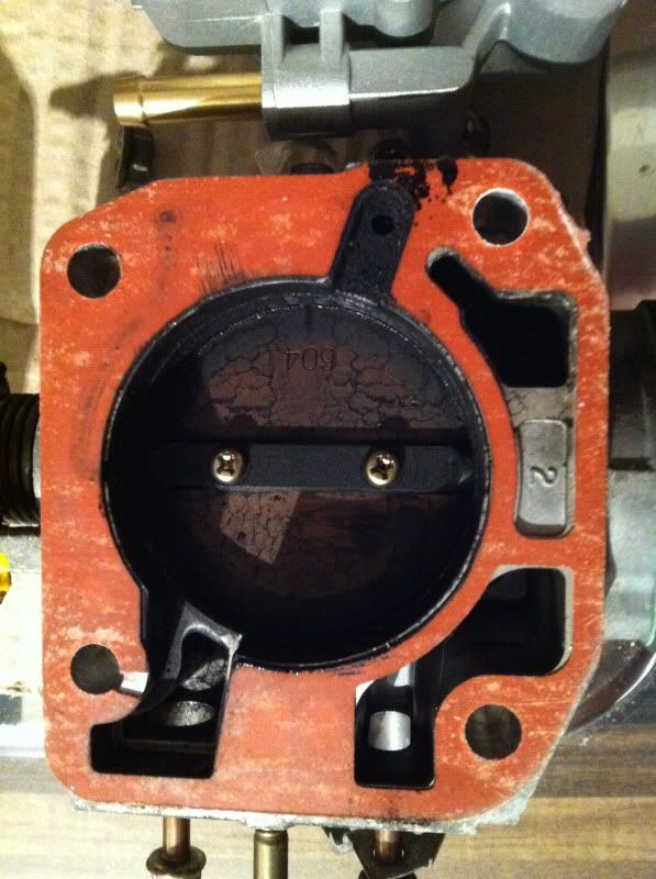
Also see the difference in the OEM intake manifold plenum (top part) compared to the JRSC inlet pipe:
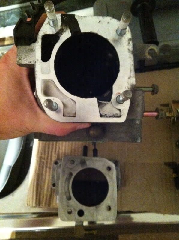
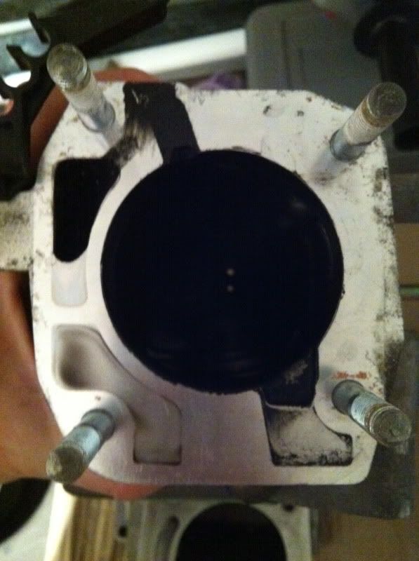
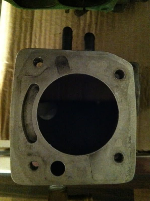
Quite different! Especially in terms of ports for various valves and air bypass.
There are a few issues / changes with this combined setup of new TB and the JRSC kits cast inlet pipe:
1) No space to connect the FITV (Fast Idle Thermo Valve). This adjusts the idle on cold starts, especially during low temps in winter. Not a big deal at all, and will be removed and binned. Anyone else installing this TB can simply re-use the existing coolant lines as it has two ports on the bottom for a bypass of the FITV. However, in the overall thinking of my build to simplify things as much as possible, I will cut these unwanted ports off and simply run the coolant line out of the IACV (Idle air control valve) straight to the back of the thermostat housing (engine side).
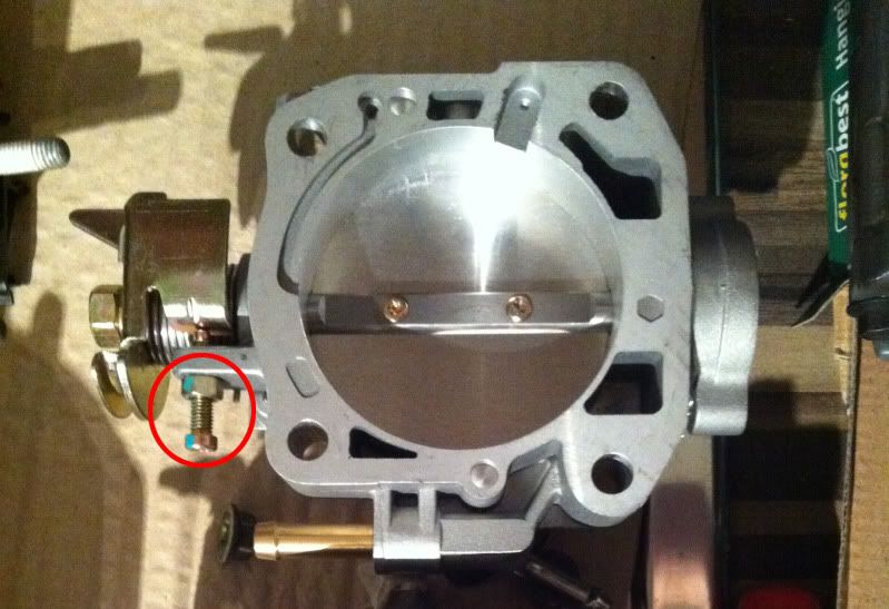
2) No Idle adjustment screw on this TB. This concerned me at first not being familiar with aftermarket TB’s, I wondered how the engine would idle with no air bypassing the TB butterfly. It can’t just rely on the IACV for the air bypass as this has a limited amount of adjustment of idle (think around 450rpm +/-). After a little reading around and many a helpful PM from Rich at Performance Autoworks and it’s a simple fix. All you need to do is adjust the throttle plate stop adjuster to allow the small opening of the butterfly. It only needs a small opening and apparently helps to stop sticking throttle as most aftermarket TB get. This screw here:
3) IACV routing of air is blocked between the aftermarket TB and the JRSC inlet pipe, see if you can work it out from the pics above – but the gist of it is, there is two brass nipples on the bottom of the JRSC inlet pipe, like so:
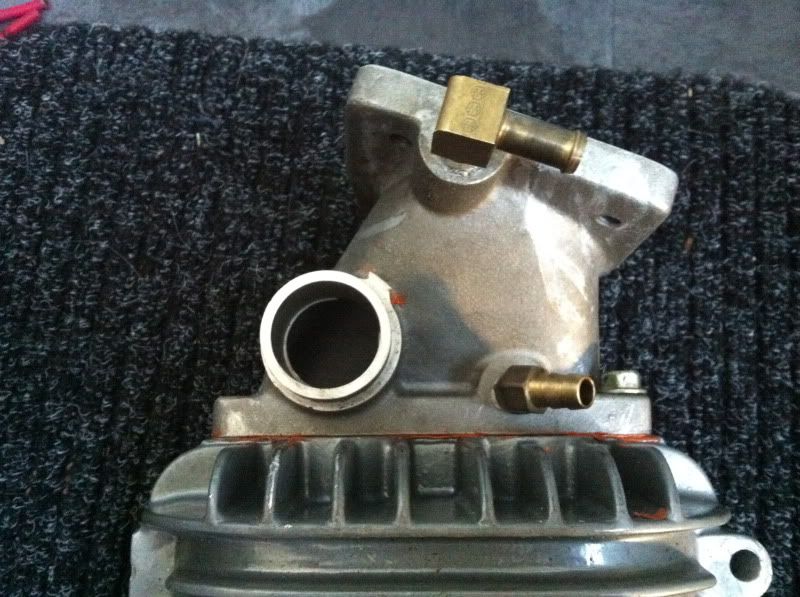
The nipple right next to the TB would normally mate up with a port on the FITV, but as pointed out this item is lost, so the port just sits open to the atmosphere of the engine bay. No good at all. The other nipple is fine as the return line from the IACV as it sits after the TB butterfly.
So to resolve the supply air from before the throttle plate I need to add a port either on the throttle body or in the intake tubing, again a fairly simple fix. It just all took a little headscratching that’s all!
Next job, which I have mentioned previously was to give the JRSC inlet pipe and other items a little DIY port and polish. But now with the larger 68mm TB, I need to match the bore size up to the JRSC inlet pipe. I’ve bought some more robust grinding stones for this job, so look for the pics on how I get on.
Exhaust system
Well originally when I bought the supercharger way back before the dinosaurs roamed the earth, I hadn’t even considered uprating the exhaust system. I had an OEM UKDM manifold and downpipe, a UKDM decat pipe and a pretty decent cat back system by Toxic Rides (essentially a Magnaflow system). But when we’re talking boost, to get the most out of a setup you need to go big. Enough people moaned to me that after forking out for a full dyno tuning session the next step would be a bigger system and would mean returning to the tuner and more cost overall. Made sense to me…but its all money at the end of the day.
Well, as with everything now, as the build has dragged on I find myself buying these desired parts as and when the opportunities arise, to supposedly complete this build ‘properly’.
3” Catback System
The first pickup was a 3” (76mm) true I.D. catback system from a guy on PUK (tonydpp). This item was pieced together by him using mandrel bent and straight pipes and an unknown straight through 3” backbox. The whole lot was welded up my Alan at Solid Fabrications and he ran it on his car for a year or so. Here it is when I picked it up from him:
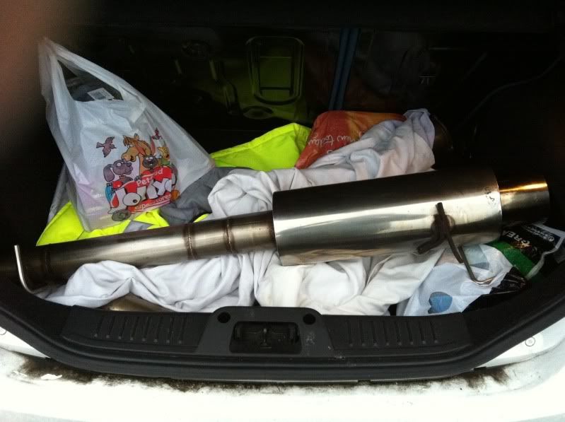

Looks pretty chunky!
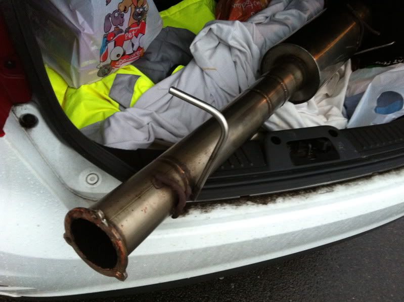
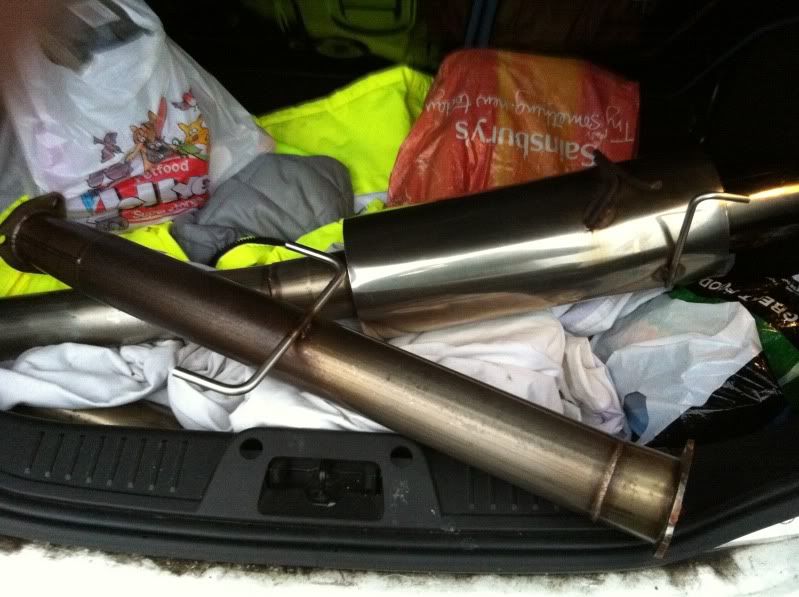
I whipped off my old system fairly sharpish to sell on and get a quick comparison of the sizes and routing:
First thing to note before someone calls me out as being a numpty, I am aware that I set the 90 degree bend near the back the wrong way!
Overall though, the routing is near as dammit, except at the rear where my old system kinks in a little to exit at the cut out in the OEM rear lip, this system comes directly out the drivers side edge of the bumper on a nice angle, looked quite good on tonydpp’s at least. Only fear is either hacking up the rear lip for a nice fit, or losing it altogether – we shall see!
I need to source some gaskets (2nr), they are an unusual choice with a thin flange and 3 bolt holes, either that or get them changed to standard 2 hole ones or get some nice V Bands???
I also need to sort out the end that meets the cat pipe, remove the section of reducer from 3” down to 2.5” and its flange, then install a new length of 3” straight pipe and a new 2 hole flange to meet the next item…the decat pipe!
3” Decat Pipe
I wondered what to do at this point, whether to run 3” or not up at the other end to the manifold. I was mostly looking at getting something custom made up by Alan at Solid Fabrications which would be based on the same rough dimensions as the Prelude OEM length. But it got me thinking come MOT time, what I would do in terms of emissions??? It fails as it is now on the map I have on my Hondata with minor mods – most likely because of the cat removed.
So I got researching other cars that I know have aftermarket 3” systems readily available and attempted to find out how long there cats were to see if anything came close. After a couple of weeks or browsing here and there, I found the PERFECT alternative!
A Mitsibushi Evo 4, 5 OR 6 ( all the same) cat is near as dammit to my UKDM cat size!
The UKDM cat dimensions are as follows - two lengths top and bottom from the outer edge of the flange to the other, because one flange is mounted on an angle = 12.5” (31.75cm) & 12.75” (32.40cm).
The Evo Cat is 13.25” (33.60cm). So only 0.75” to 0.5” difference in length, something which I think could have been lost in the fitment of the hangers but as I’m having to redo the catback end by removing the reducer, the length I put back can be exactly enough to make the whole system fit perfectly!
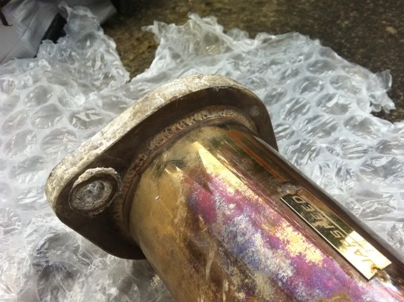
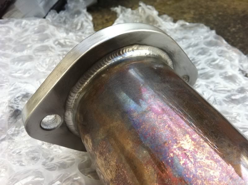
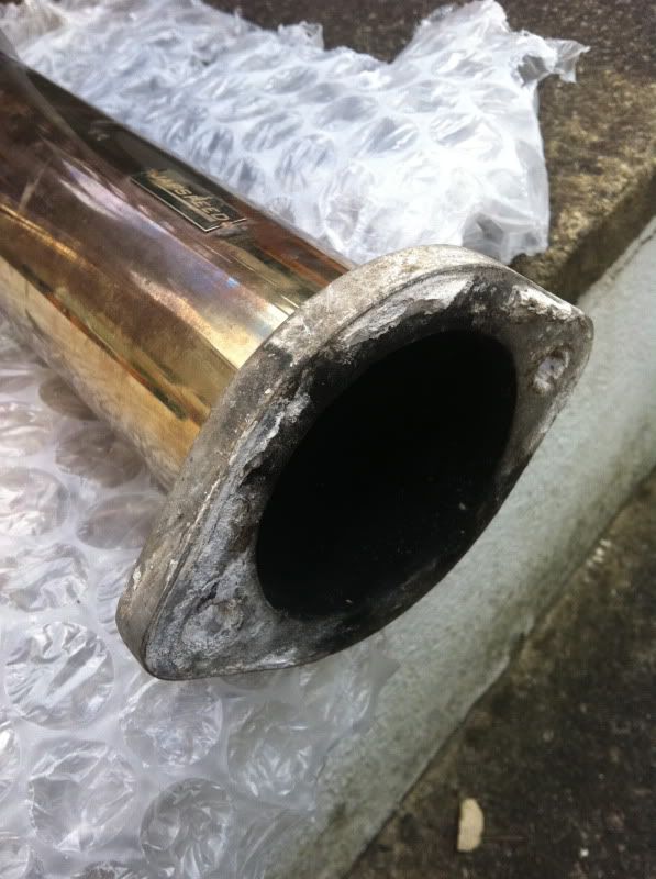
So I went on the hunt for an Evo 4/5/6 decat pipe and managed to pick up this Japspeed item for cheap, which is also a true 3” (76mm) I.D. decat:
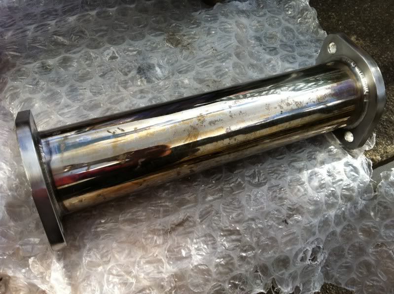
As I posted in the how-to section, this cleaned up a treat with a wire brush wheel on a drill and some Autosol:
Following this pickup I need some gaskets to mate the decat up and picked up these from a place on ebay called Midlands Exhausts, which have a high temp sealed inner edge to supposedly avoid premature leaks. They look good for the money:
I have various newish stainless steel bolts from my old system, but may need to get some more to complete the new setup completely.
OEM Evo 6 Catalyst Converter
Next up was to source an Evo 4, 5 or 6 catalyst converter for MOT times, I was in no rush to buy this one with the project off the road for so long, so played the waiting game watching various ones on ebay and managed to pick one up for £45 delivered, which was good as most were being sold between £50-100 + postage on top. And to make it even better rather than picking up an Evo 4 item, which would be older and more used, this one is fresh off an Evo 6, the newest I could have got second hand from the model choices. Win, win!
Here she is:
Need to add pic!
So I’ll give this a whirl when it comes to getting it back on the road. I’ll try it with or without for comparisons, luckily the MOT guy is my best mate, so I can get some comparison runs in no problem.
Custom Manifold
Final piece of the jigsaw and the weakest link in my current system was my OEM manifold and downpipe. The UKDM one in particular is slightly more restrictive than the OEM JDM manifold, and with the supercharger slapped on will be waaaaaaay restrictive, so it just had to go. From the word go I wanted Alan at Solid Fabrications (http://solid-fabrications.co.uk/) to make me a custom setup and as time went on, the opportunity arose.
So a little research as to what design works best with JRSC’d ludes was next on my googling sessions!
The main manifold I found people using was the Kamikaze ‘header’. A few people in the UK have had one of these. They are a 4-1 design as opposed to the usual 4-2-1 design of most systems for our cars. These headers traditionally are supposed to yield more gains in the high rev range but lose some low end torque, and vice versa for the 4-2-1. No proof that I’ve seen back to back, just what ‘people say’. However, the JRSC power comes in so early (2kish) and improves the torque so much that this negates the downside of a 4-1 design. Here’s that system, which I nearly bought:
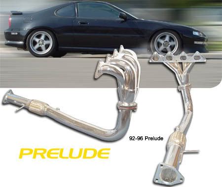
http://www.kamikazeperformance.com/stor ... 6884.10673
Here’s one in a black finish:
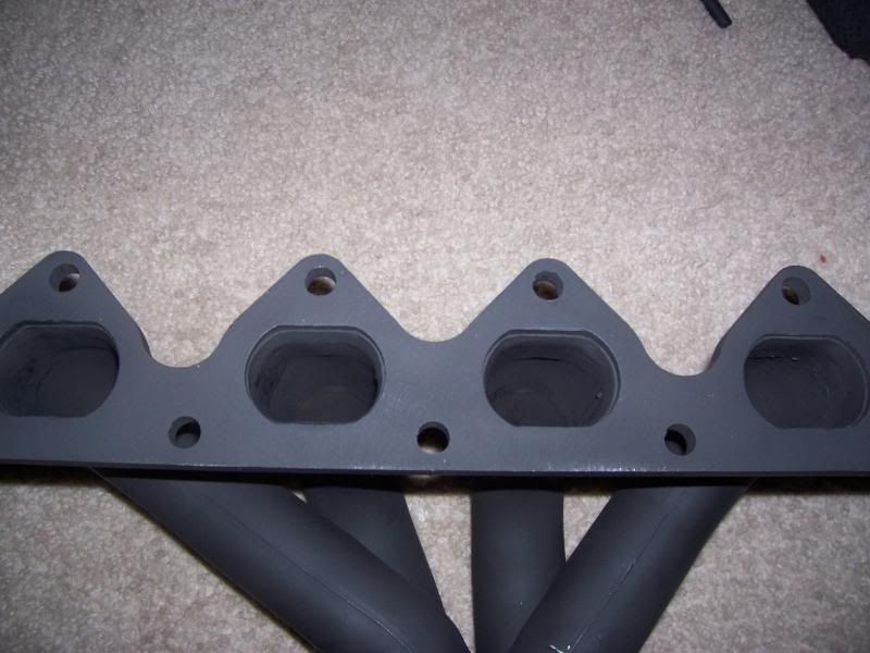


Also reading the couple of books I have on Supercharging (see early posts on Page 1/2) has sections on header and exhaust design and states that the simplest, quickest and shortest route for the gases on SC applications is the best. So short primaries and a collector as soon as possible yields the best gains – hence the 4-1 design that is so popular. Some modify the collector on the Kamikaze to make a true 2.5” collector and downpipe and then open up to 3” cat and catback.
But it still seemed restrictive to me and with shipping and duty charge, I may as well put my money into Alan to make something a little more special, but with the car in pieces in the garage, I had to give him something to go on to make it…
The best system I found for a similar setup was for the JRSC kit on B series engines and is made by the supercharger experts LHT Performance, who make the only custom intake manifolds to allow water cooling to the intake charge (manifold is at the bottom of the page):
http://lhtperformance.net/documents/supercharge.html
Before anyone says, yes they state they have a charge cooler for the H22A – Many have been down that avenue contacting them about it the past year and LHT havn’t replied? There’s no pics of a completed one either, so it’s either in R&D or just hype. If one comes to light, I’ll rip there arm off for one!
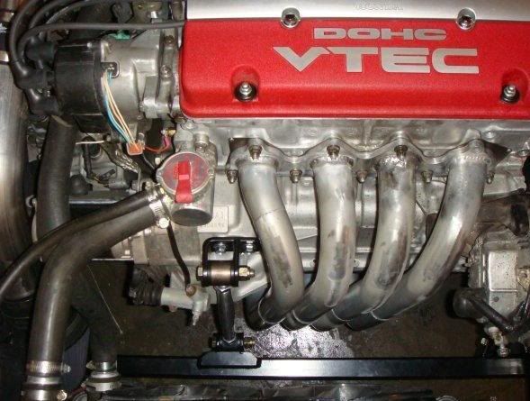
Here’s the manifold:
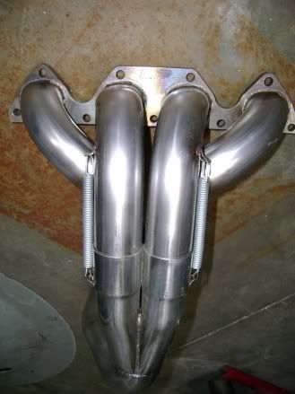
So, they say they tested against many other off the shelf ‘SC’ exhausts and this beat them by far (most likely with the 3.0” collector for their 300WHP Supercharged CRX!).
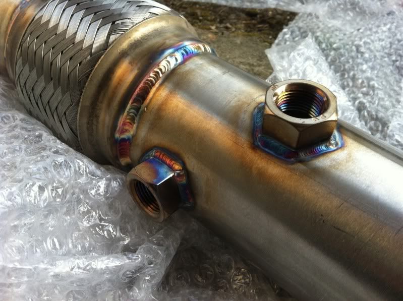
So that was it! There’s my design for the build. Using as large a primary as he could to crush and mate to the exhaust ports of the engine (not measured these yet) this will then go straight into a 4 branch collector and then a flange roughly where the OEM one sat. We discussed about using sleeves and springs like the LHT one for movement, but ultimately they will leak a little here and there. So I decided on the bolted flange and included a flexi pipe on the downpipe like the OEM setup. The collector chosen was the full 3” from the manifold down, all the way to the decat pipe. He used the same length as the OEM manifold and downpipe and welded the end cat flange on. I will mate it all up and take up any differences in the length with the catbacks reducer and flange removal. Only other thing to mention was the downpipe having two O2 ports welded in place, one in the factory location for the OEM O2 sensor and one further round the side for my AEM wideband’s Bosch sensor to plug into.
I took a stack of measurements of the engine block and sub frame clearances and sent these and the pics of the LHT above over in an email and couriered him my old OEM manifold to design off of.
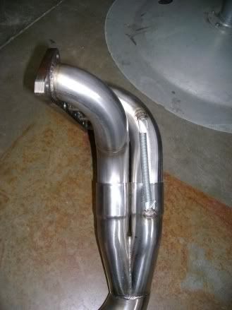
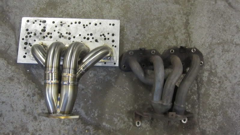
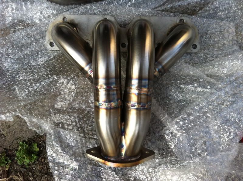
Fair play to Alan, his skills of building something so blindly without physically having the car to hand is testament to his expertise. From the minute I measured clearances I knew the front sub frame was going to be an issue…but more on that later. Let’s see what he made me! Teaser pics he emailed me during the work, 1st batch when he’d done the top half:
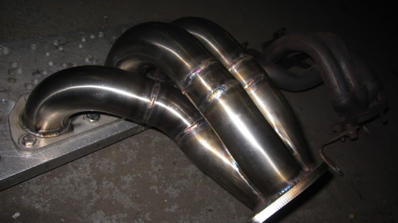
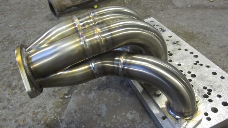
2nd batch of pics when he’d progressed to the downpipe:
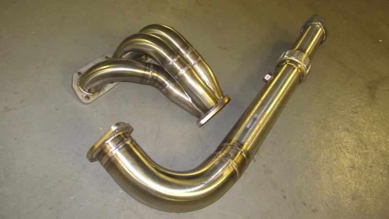
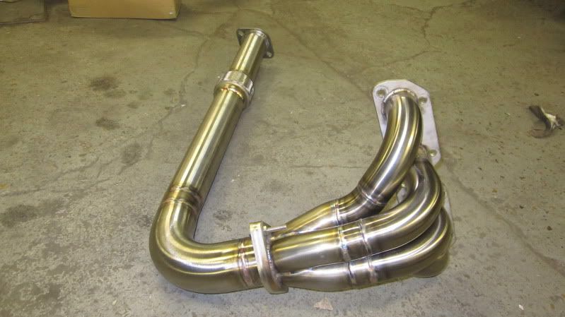
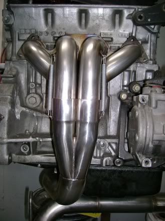
Then before I knew it, he had it winging its way back to me via courier! Best parcel I’ve had delivered since the supercharger I think. Opening it like a kid at Xmas, I was greeted with this:
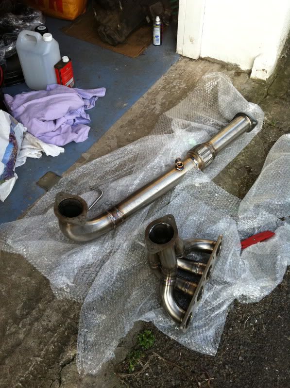
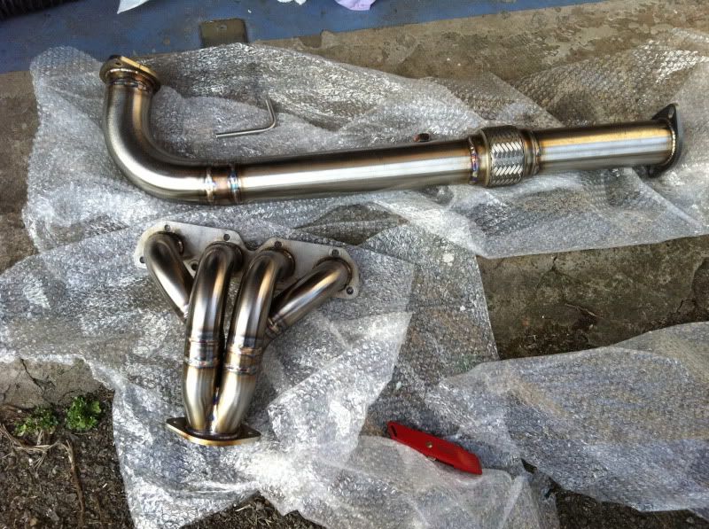
How frickin sweet is that!
Many thanks Alan – can’t rate your services enough!
Misc – S/S studs & nuts / New O2 sensor / Cross member
Stainless steel manifold studs and nuts
While removing my old manifold one of the studs came out with the nut and I thought they looked a little weary and had potential to shear one day. As I’d be tarting up the engine with some paint, I didn’t want a leak appearing and messing that up. Plus these would be all shiny and new, just like my new manifold. I had these in my ebay watched list for too long and at £15 delivered seemed a bargain not to buy now:
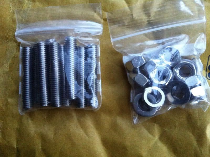
Sexy stuff – the same studs will do the rear engines intake manifold studs too, but I’ve left these as the originals.
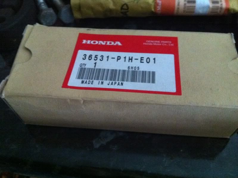
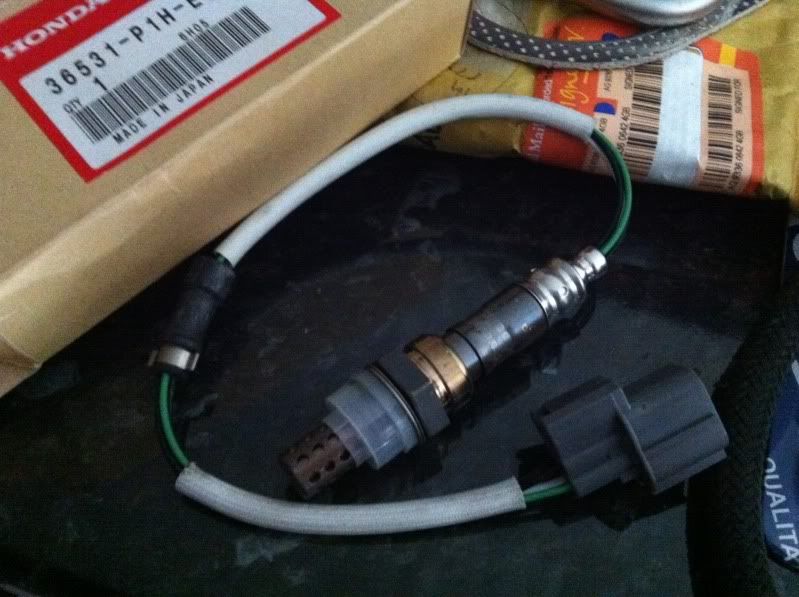
New Honda O2 sensor
I also decided to get a new O2 sensor. My old one works fine, but figured I’d want the system working 100% for tuning and running. Plus I was tempted by an original Honda item for a Civic, which is identical, give or take ever so slightly longer wires.
Good stuff!
Exhaust manifold gasket
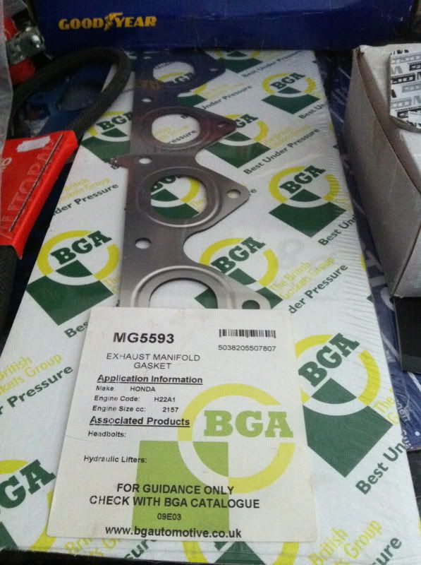
Just a pic for this one, shows the BGA part number for info.
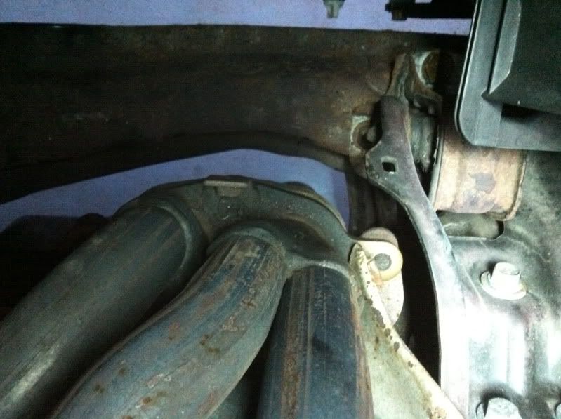
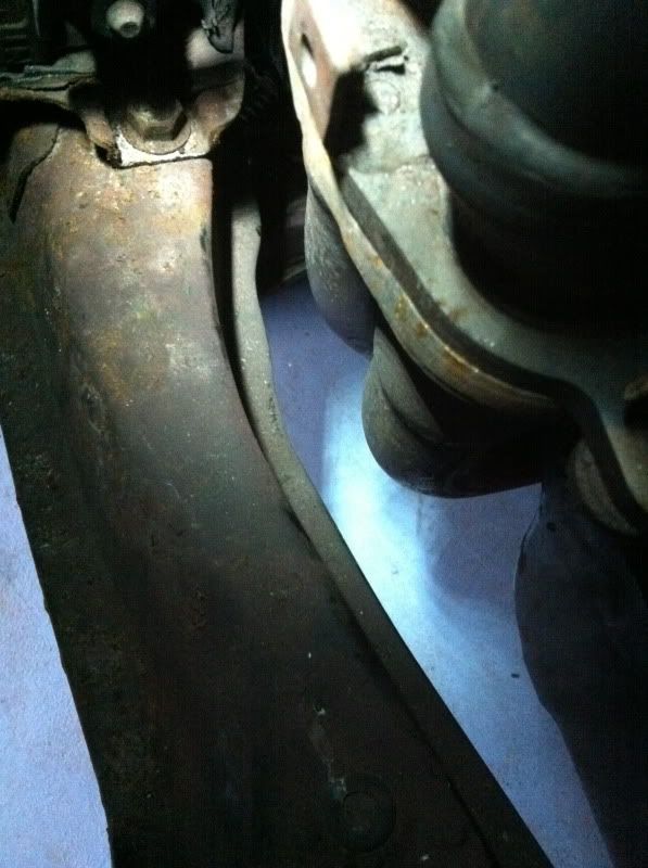
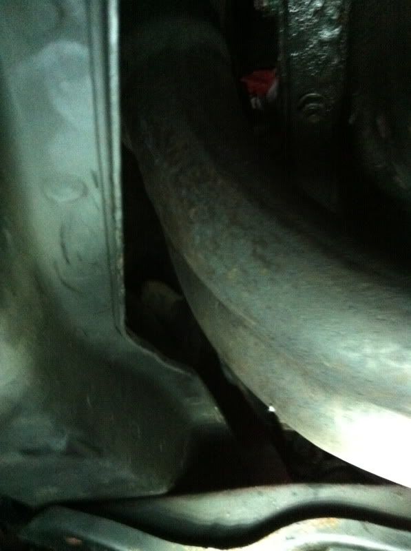
Cross member mods
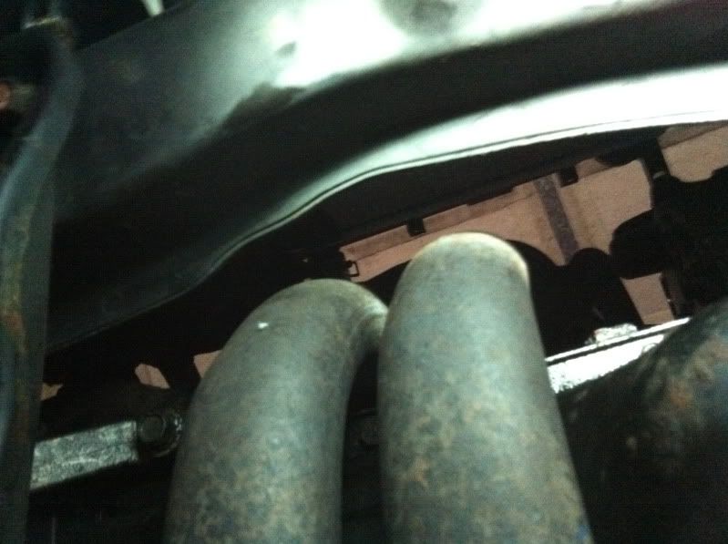
When I measured the clearances of the new exhaust manifold and downpipe, I knew straight away I’d have to remove at least 0.5” around the downpipe and that was if Alan confidently went as close to the engine tolerance as possible. He didn’t, but that’s what you get with not providing the car. As a result the amount is looking anywhere between 1” and 1.5” to cut out and re-weld up to strengthen it! Yay!
Here is how things looked with the OEM downpipe clearance to give you an idea:
I did start to look into Traction bars from the likes of Explicit Speed (ESP) & similar setups as these sit closer to the front of the car and are about 1/3 the width as the OEM one. Something like this:
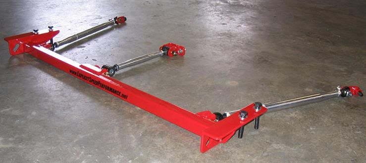
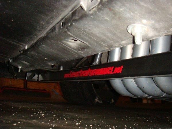
Tasty stuff and would certainly help combat wheel hop. But the price and lack of shipping options has thrown this goody out (for now!). I also have their engine mount set in mind for future parts.
So that’s it really on the cross member –it’s in the way, so I’ll cut it and re-weld it. Simples!
That’s everything on parts for now (thank god), next update I’ll go back into the build and should be posting asap!
Cheers,
Rob
Intake & Exhuast
Intake system
Well, as with a lot of things in my build, this wasn’t in my initial plans but as time goes on and parts crop up I find myself buying more and more to make the build a little more interesting!
First up I had discounted a larger throttle body (TB), mainly because of the expense and secondly because of the limits of the size of the TB to the JRSC kits cast inlet pipe. I hadn’t looked into it much in the early days, but now with the kit in hand and measurements taken, it looked to be that 68mm would be the safe limit to go without having to add some welding material into an open port of the inlet pipe. So I looked for a budget aftermarket TB, I wasn’t concerned with the big bucks CNC items from Skunk2, plus I’ve heard of them sticking more so than cast items. So fell upon this one, which a couple of guys have used and rated now – a CNT 68mm cast TB which comes with a 68mm matched gasket and a brand new TPS (throttle position sensor) & gasket too – a bonus! Here’s some pics:
As you can see the engine side is 68mm, but the opening to the intake tubing tapers out to around 71.5mm. Should add some minor improvement to the setup and give some improved throttle response.
Here is how it compares with the OEM throttle body:
Also see the difference in the OEM intake manifold plenum (top part) compared to the JRSC inlet pipe:
Quite different! Especially in terms of ports for various valves and air bypass.
There are a few issues / changes with this combined setup of new TB and the JRSC kits cast inlet pipe:
1) No space to connect the FITV (Fast Idle Thermo Valve). This adjusts the idle on cold starts, especially during low temps in winter. Not a big deal at all, and will be removed and binned. Anyone else installing this TB can simply re-use the existing coolant lines as it has two ports on the bottom for a bypass of the FITV. However, in the overall thinking of my build to simplify things as much as possible, I will cut these unwanted ports off and simply run the coolant line out of the IACV (Idle air control valve) straight to the back of the thermostat housing (engine side).
2) No Idle adjustment screw on this TB. This concerned me at first not being familiar with aftermarket TB’s, I wondered how the engine would idle with no air bypassing the TB butterfly. It can’t just rely on the IACV for the air bypass as this has a limited amount of adjustment of idle (think around 450rpm +/-). After a little reading around and many a helpful PM from Rich at Performance Autoworks and it’s a simple fix. All you need to do is adjust the throttle plate stop adjuster to allow the small opening of the butterfly. It only needs a small opening and apparently helps to stop sticking throttle as most aftermarket TB get. This screw here:
3) IACV routing of air is blocked between the aftermarket TB and the JRSC inlet pipe, see if you can work it out from the pics above – but the gist of it is, there is two brass nipples on the bottom of the JRSC inlet pipe, like so:
The nipple right next to the TB would normally mate up with a port on the FITV, but as pointed out this item is lost, so the port just sits open to the atmosphere of the engine bay. No good at all. The other nipple is fine as the return line from the IACV as it sits after the TB butterfly.
So to resolve the supply air from before the throttle plate I need to add a port either on the throttle body or in the intake tubing, again a fairly simple fix. It just all took a little headscratching that’s all!
Next job, which I have mentioned previously was to give the JRSC inlet pipe and other items a little DIY port and polish. But now with the larger 68mm TB, I need to match the bore size up to the JRSC inlet pipe. I’ve bought some more robust grinding stones for this job, so look for the pics on how I get on.
Exhaust system
Well originally when I bought the supercharger way back before the dinosaurs roamed the earth, I hadn’t even considered uprating the exhaust system. I had an OEM UKDM manifold and downpipe, a UKDM decat pipe and a pretty decent cat back system by Toxic Rides (essentially a Magnaflow system). But when we’re talking boost, to get the most out of a setup you need to go big. Enough people moaned to me that after forking out for a full dyno tuning session the next step would be a bigger system and would mean returning to the tuner and more cost overall. Made sense to me…but its all money at the end of the day.
Well, as with everything now, as the build has dragged on I find myself buying these desired parts as and when the opportunities arise, to supposedly complete this build ‘properly’.
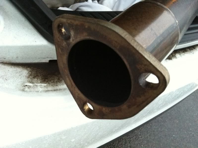
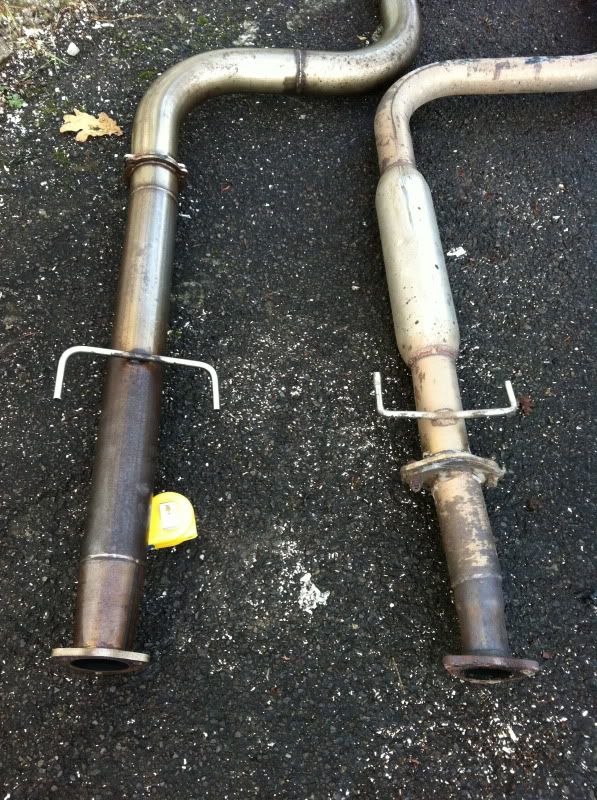
3” Catback System
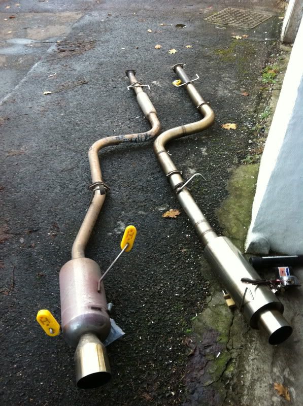
The first pickup was a 3” (76mm) true I.D. catback system from a guy on PUK (tonydpp). This item was pieced together by him using mandrel bent and straight pipes and an unknown straight through 3” backbox. The whole lot was welded up my Alan at Solid Fabrications and he ran it on his car for a year or so. Here it is when I picked it up from him:
Looks pretty chunky!
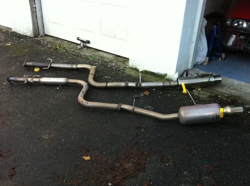
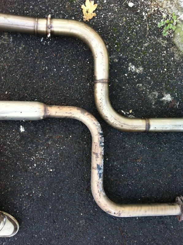
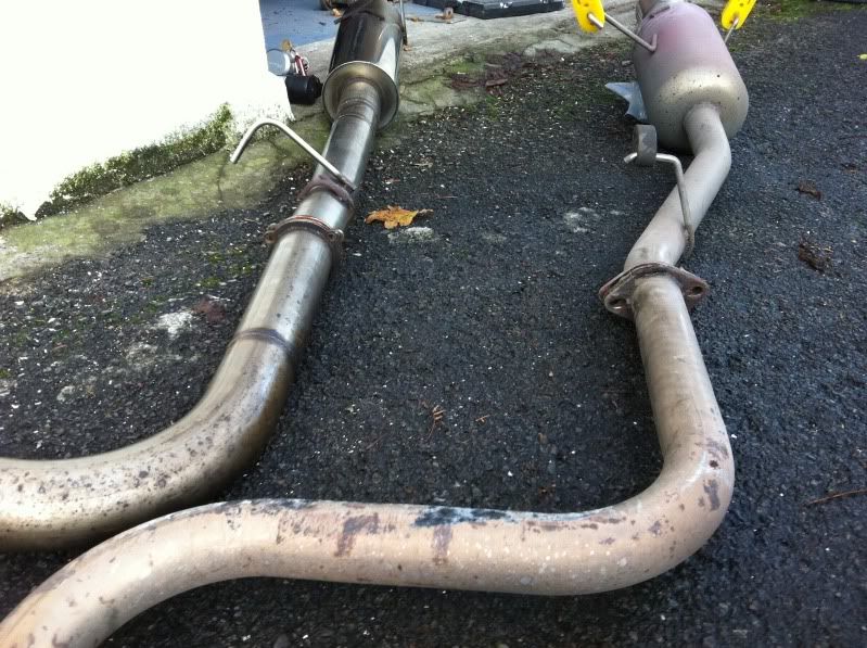
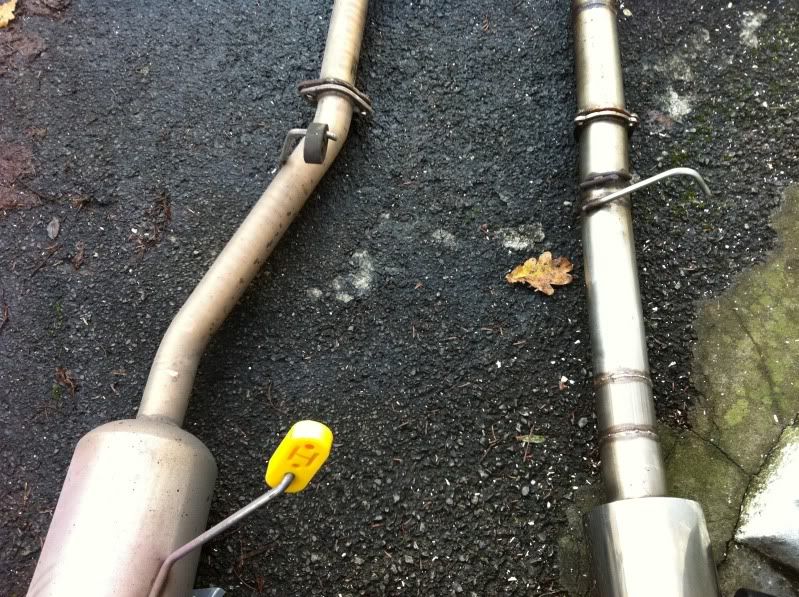
I whipped off my old system fairly sharpish to sell on and get a quick comparison of the sizes and routing:
First thing to note before someone calls me out as being a numpty, I am aware that I set the 90 degree bend near the back the wrong way!
Overall though, the routing is near as dammit, except at the rear where my old system kinks in a little to exit at the cut out in the OEM rear lip, this system comes directly out the drivers side edge of the bumper on a nice angle, looked quite good on tonydpp’s at least. Only fear is either hacking up the rear lip for a nice fit, or losing it altogether – we shall see!
I need to source some gaskets (2nr), they are an unusual choice with a thin flange and 3 bolt holes, either that or get them changed to standard 2 hole ones or get some nice V Bands???
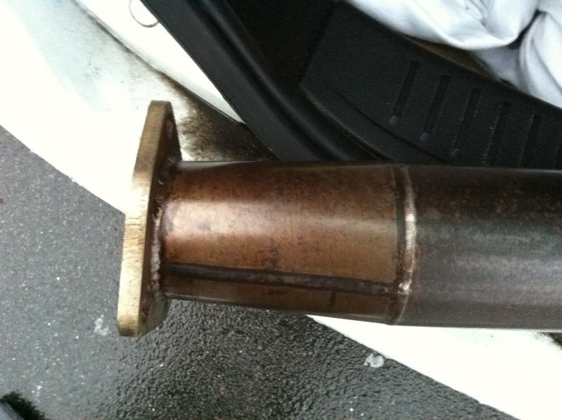
I also need to sort out the end that meets the cat pipe, remove the section of reducer from 3” down to 2.5” and its flange, then install a new length of 3” straight pipe and a new 2 hole flange to meet the next item…the decat pipe!
3” Decat Pipe
I wondered what to do at this point, whether to run 3” or not up at the other end to the manifold. I was mostly looking at getting something custom made up by Alan at Solid Fabrications which would be based on the same rough dimensions as the Prelude OEM length. But it got me thinking come MOT time, what I would do in terms of emissions??? It fails as it is now on the map I have on my Hondata with minor mods – most likely because of the cat removed.
So I got researching other cars that I know have aftermarket 3” systems readily available and attempted to find out how long there cats were to see if anything came close. After a couple of weeks or browsing here and there, I found the PERFECT alternative!
A Mitsibushi Evo 4, 5 OR 6 ( all the same) cat is near as dammit to my UKDM cat size!
The UKDM cat dimensions are as follows - two lengths top and bottom from the outer edge of the flange to the other, because one flange is mounted on an angle = 12.5” (31.75cm) & 12.75” (32.40cm).
The Evo Cat is 13.25” (33.60cm). So only 0.75” to 0.5” difference in length, something which I think could have been lost in the fitment of the hangers but as I’m having to redo the catback end by removing the reducer, the length I put back can be exactly enough to make the whole system fit perfectly!
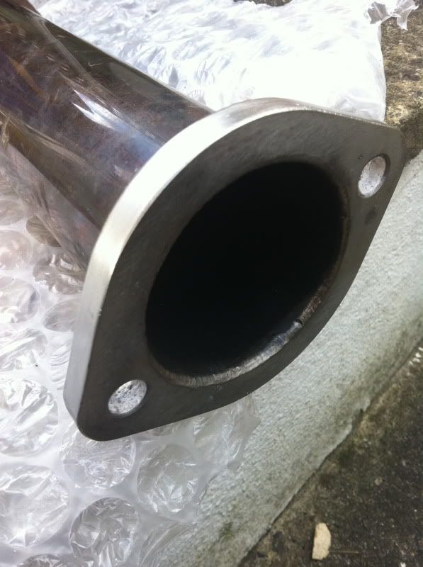
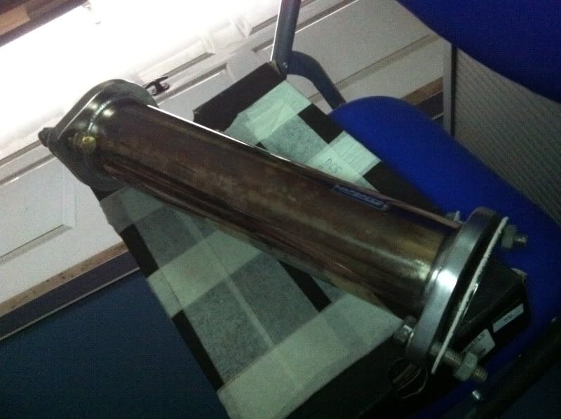
So I went on the hunt for an Evo 4/5/6 decat pipe and managed to pick up this Japspeed item for cheap, which is also a true 3” (76mm) I.D. decat:
As I posted in the how-to section, this cleaned up a treat with a wire brush wheel on a drill and some Autosol:
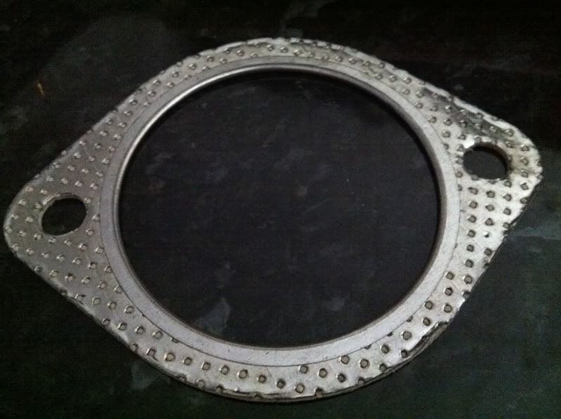
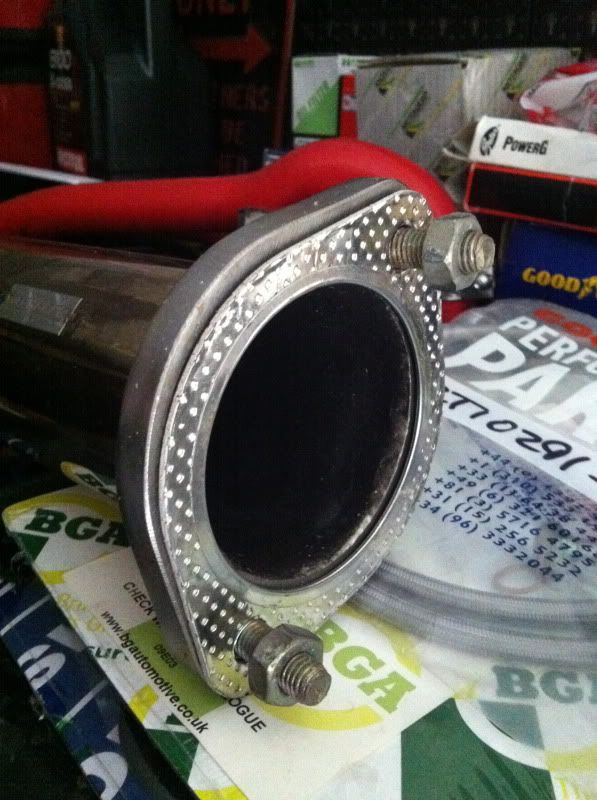
Following this pickup I need some gaskets to mate the decat up and picked up these from a place on ebay called Midlands Exhausts, which have a high temp sealed inner edge to supposedly avoid premature leaks. They look good for the money:
I have various newish stainless steel bolts from my old system, but may need to get some more to complete the new setup completely.
OEM Evo 6 Catalyst Converter
Next up was to source an Evo 4, 5 or 6 catalyst converter for MOT times, I was in no rush to buy this one with the project off the road for so long, so played the waiting game watching various ones on ebay and managed to pick one up for £45 delivered, which was good as most were being sold between £50-100 + postage on top. And to make it even better rather than picking up an Evo 4 item, which would be older and more used, this one is fresh off an Evo 6, the newest I could have got second hand from the model choices. Win, win!
Here she is:
Need to add pic!
So I’ll give this a whirl when it comes to getting it back on the road. I’ll try it with or without for comparisons, luckily the MOT guy is my best mate, so I can get some comparison runs in no problem.
Custom Manifold
Final piece of the jigsaw and the weakest link in my current system was my OEM manifold and downpipe. The UKDM one in particular is slightly more restrictive than the OEM JDM manifold, and with the supercharger slapped on will be waaaaaaay restrictive, so it just had to go. From the word go I wanted Alan at Solid Fabrications (http://solid-fabrications.co.uk/) to make me a custom setup and as time went on, the opportunity arose.
So a little research as to what design works best with JRSC’d ludes was next on my googling sessions!
The main manifold I found people using was the Kamikaze ‘header’. A few people in the UK have had one of these. They are a 4-1 design as opposed to the usual 4-2-1 design of most systems for our cars. These headers traditionally are supposed to yield more gains in the high rev range but lose some low end torque, and vice versa for the 4-2-1. No proof that I’ve seen back to back, just what ‘people say’. However, the JRSC power comes in so early (2kish) and improves the torque so much that this negates the downside of a 4-1 design. Here’s that system, which I nearly bought:
http://www.kamikazeperformance.com/stor ... 6884.10673
Here’s one in a black finish:
Also reading the couple of books I have on Supercharging (see early posts on Page 1/2) has sections on header and exhaust design and states that the simplest, quickest and shortest route for the gases on SC applications is the best. So short primaries and a collector as soon as possible yields the best gains – hence the 4-1 design that is so popular. Some modify the collector on the Kamikaze to make a true 2.5” collector and downpipe and then open up to 3” cat and catback.
But it still seemed restrictive to me and with shipping and duty charge, I may as well put my money into Alan to make something a little more special, but with the car in pieces in the garage, I had to give him something to go on to make it…
The best system I found for a similar setup was for the JRSC kit on B series engines and is made by the supercharger experts LHT Performance, who make the only custom intake manifolds to allow water cooling to the intake charge (manifold is at the bottom of the page):
http://lhtperformance.net/documents/supercharge.html
Before anyone says, yes they state they have a charge cooler for the H22A – Many have been down that avenue contacting them about it the past year and LHT havn’t replied? There’s no pics of a completed one either, so it’s either in R&D or just hype. If one comes to light, I’ll rip there arm off for one!
Here’s the manifold:
So, they say they tested against many other off the shelf ‘SC’ exhausts and this beat them by far (most likely with the 3.0” collector for their 300WHP Supercharged CRX!).
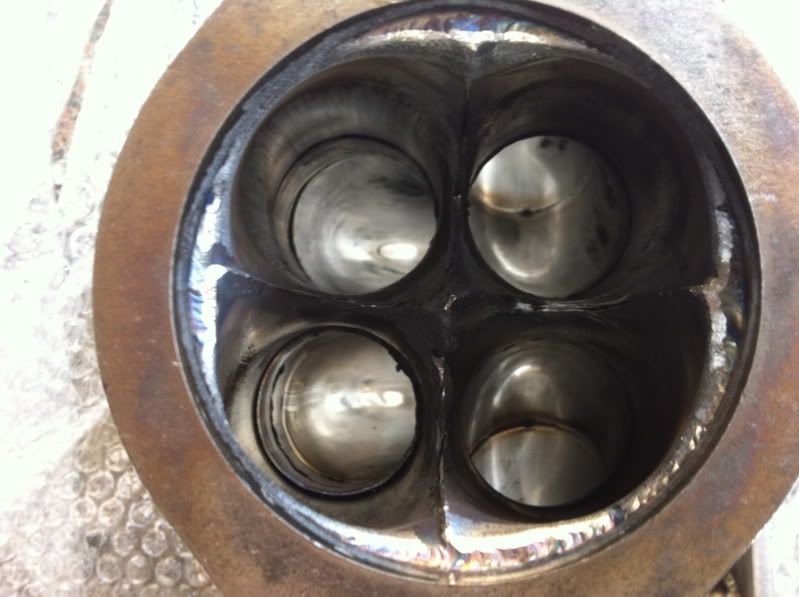
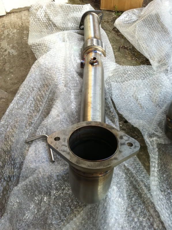
So that was it! There’s my design for the build. Using as large a primary as he could to crush and mate to the exhaust ports of the engine (not measured these yet) this will then go straight into a 4 branch collector and then a flange roughly where the OEM one sat. We discussed about using sleeves and springs like the LHT one for movement, but ultimately they will leak a little here and there. So I decided on the bolted flange and included a flexi pipe on the downpipe like the OEM setup. The collector chosen was the full 3” from the manifold down, all the way to the decat pipe. He used the same length as the OEM manifold and downpipe and welded the end cat flange on. I will mate it all up and take up any differences in the length with the catbacks reducer and flange removal. Only other thing to mention was the downpipe having two O2 ports welded in place, one in the factory location for the OEM O2 sensor and one further round the side for my AEM wideband’s Bosch sensor to plug into.
I took a stack of measurements of the engine block and sub frame clearances and sent these and the pics of the LHT above over in an email and couriered him my old OEM manifold to design off of.
Fair play to Alan, his skills of building something so blindly without physically having the car to hand is testament to his expertise. From the minute I measured clearances I knew the front sub frame was going to be an issue…but more on that later. Let’s see what he made me! Teaser pics he emailed me during the work, 1st batch when he’d done the top half:
2nd batch of pics when he’d progressed to the downpipe:
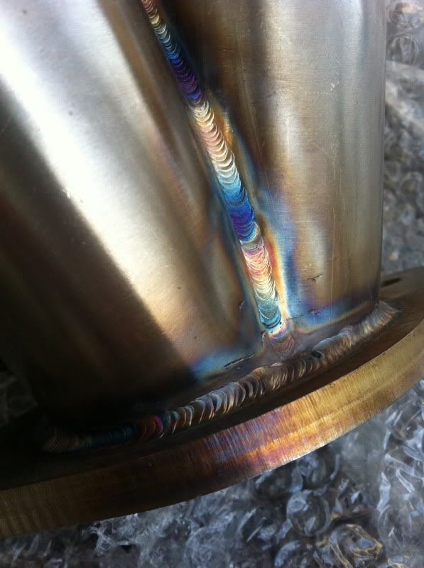
Then before I knew it, he had it winging its way back to me via courier! Best parcel I’ve had delivered since the supercharger I think. Opening it like a kid at Xmas, I was greeted with this:
How frickin sweet is that!
Many thanks Alan – can’t rate your services enough!
Misc – S/S studs & nuts / New O2 sensor / Cross member
Stainless steel manifold studs and nuts
While removing my old manifold one of the studs came out with the nut and I thought they looked a little weary and had potential to shear one day. As I’d be tarting up the engine with some paint, I didn’t want a leak appearing and messing that up. Plus these would be all shiny and new, just like my new manifold. I had these in my ebay watched list for too long and at £15 delivered seemed a bargain not to buy now:
Sexy stuff – the same studs will do the rear engines intake manifold studs too, but I’ve left these as the originals.
New Honda O2 sensor
I also decided to get a new O2 sensor. My old one works fine, but figured I’d want the system working 100% for tuning and running. Plus I was tempted by an original Honda item for a Civic, which is identical, give or take ever so slightly longer wires.
Good stuff!
Exhaust manifold gasket
Just a pic for this one, shows the BGA part number for info.
Cross member mods
When I measured the clearances of the new exhaust manifold and downpipe, I knew straight away I’d have to remove at least 0.5” around the downpipe and that was if Alan confidently went as close to the engine tolerance as possible. He didn’t, but that’s what you get with not providing the car. As a result the amount is looking anywhere between 1” and 1.5” to cut out and re-weld up to strengthen it! Yay!
Here is how things looked with the OEM downpipe clearance to give you an idea:
I did start to look into Traction bars from the likes of Explicit Speed (ESP) & similar setups as these sit closer to the front of the car and are about 1/3 the width as the OEM one. Something like this:
Tasty stuff and would certainly help combat wheel hop. But the price and lack of shipping options has thrown this goody out (for now!). I also have their engine mount set in mind for future parts.
So that’s it really on the cross member –it’s in the way, so I’ll cut it and re-weld it. Simples!
That’s everything on parts for now (thank god), next update I’ll go back into the build and should be posting asap!
Cheers,
Rob
-
NafemanNathan
- LotM Winner
- Posts: 20144
- Joined: Sun Aug 08, 2010 9:37 pm
- My Generation: 0G
- Location: Yeovil, Somerset
- Has thanked: 8 times
- Been thanked: 124 times