BUILD PART 5) - Build (Cont'd) – JRSC parts/Intake refurb & more
JRSC parts mock up
Right last update had the intake manifold removed and the JRSC parts sneaked into the house:
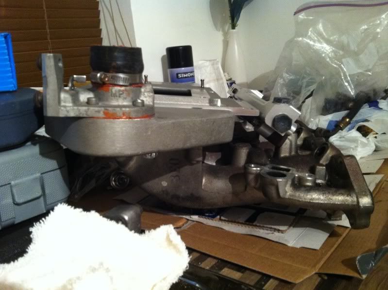
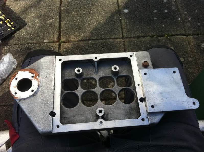
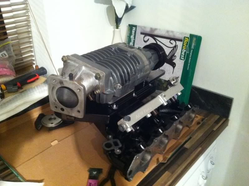
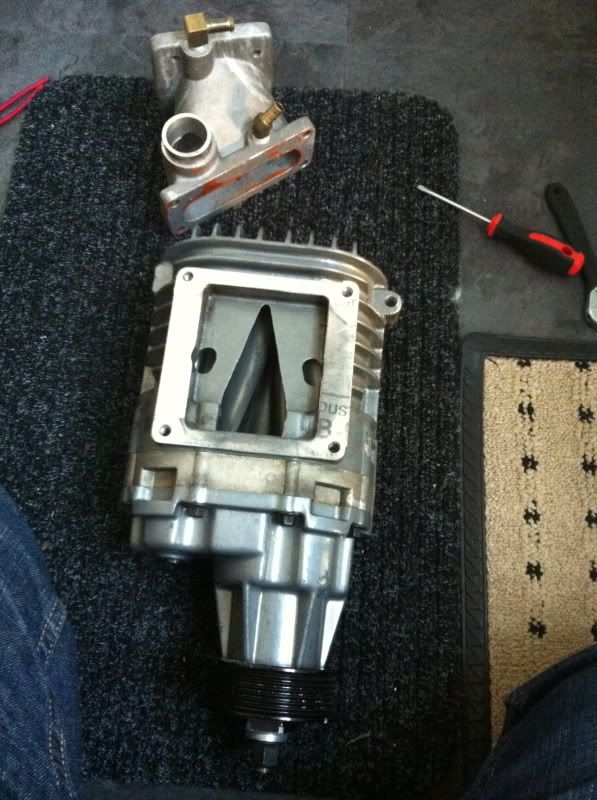
So I mounted the JRSC plenum, with bypass valve attached. This piece mounts the supercharger and the jackshaft assembly (to the right). It makes more sense as the write up goes on with pics.

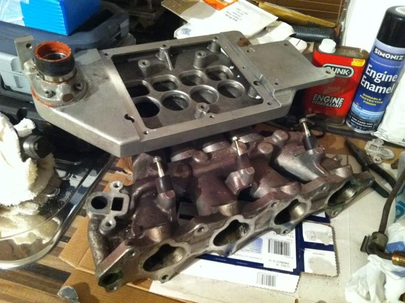
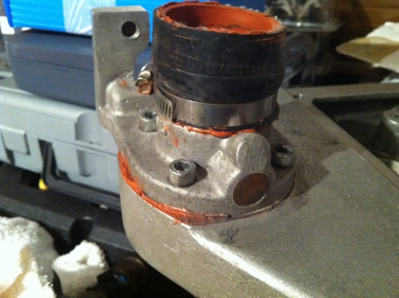
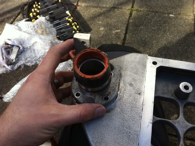
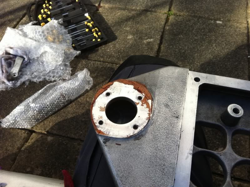
A close up of the bypass valve. This is missing the vacuum diaphragm element, which is to one side. This is what moves the small butterfly inside dependent upon vacuum / boost conditions. Also note the masses of orange gunk spilling out from joints, this has been my biggest annoyance of the kit. It’s instant gasket, and whoever fitted the kit before I got it, used tons of it on every joining part. Even that top plenum had it on the main supercharger opening but I’ve cleaned a lot of it off before taking pics.

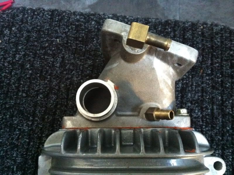
Now add the supercharger mounting plate – this also has a number of vacuum ports for various things and a large port for the brake booster. This item is actually brand new from Jackson Racing. The seller sourced it because the old one had been dropped and damaged. This piece also has the area to mount the IACV relocation part (front thin flat area):
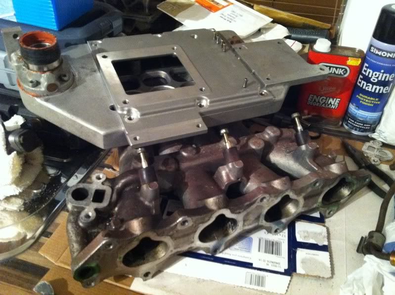
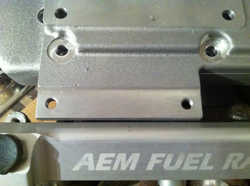
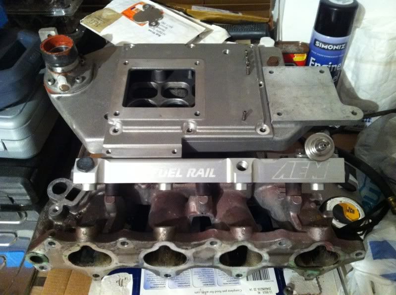
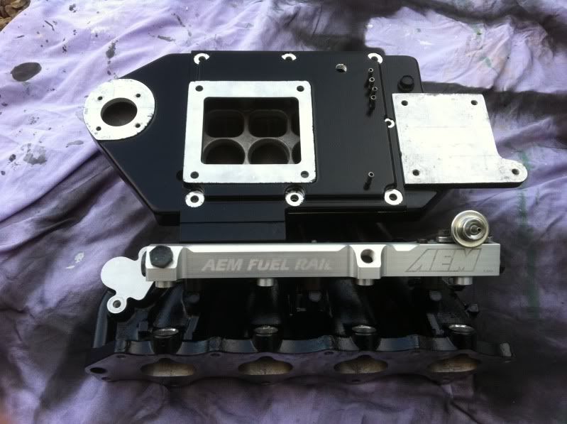
Next up, mount my AEM fuel rail, this came very close to the IACV mounting part of the mounting plate:
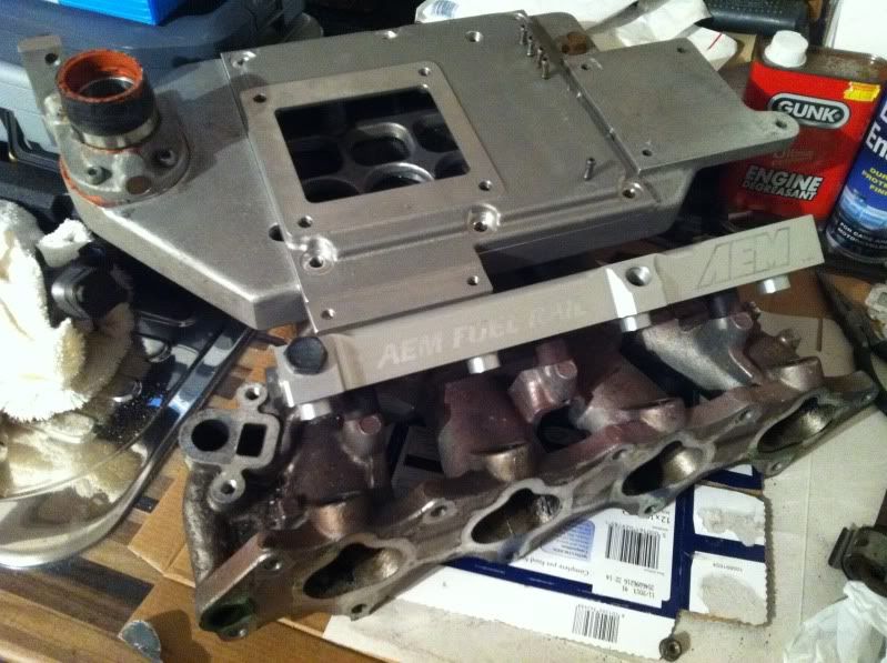
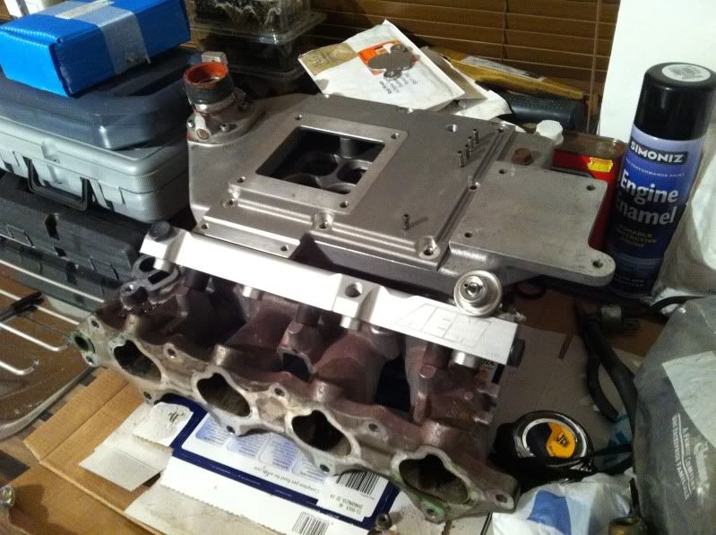
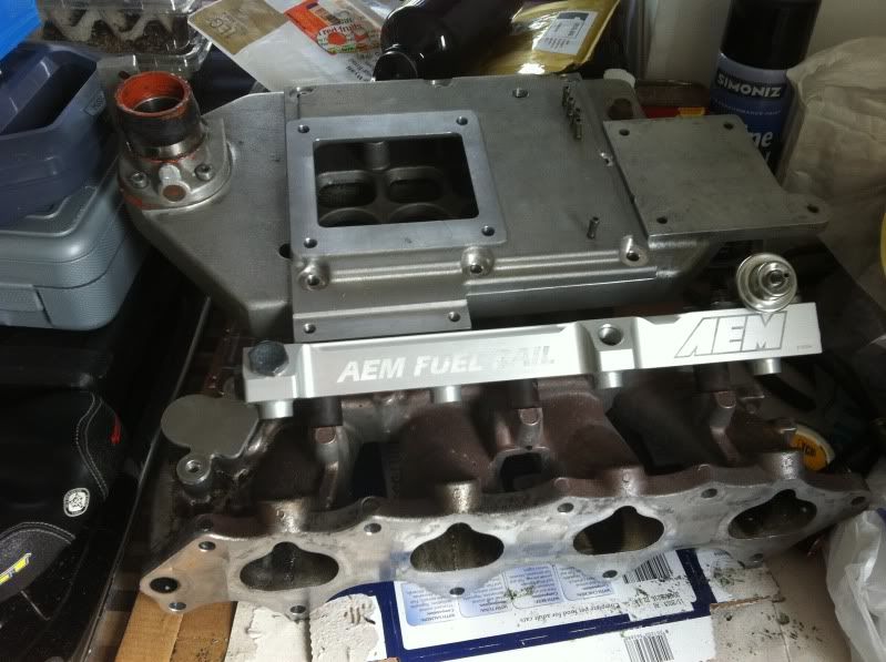
Some more pics from different angles:
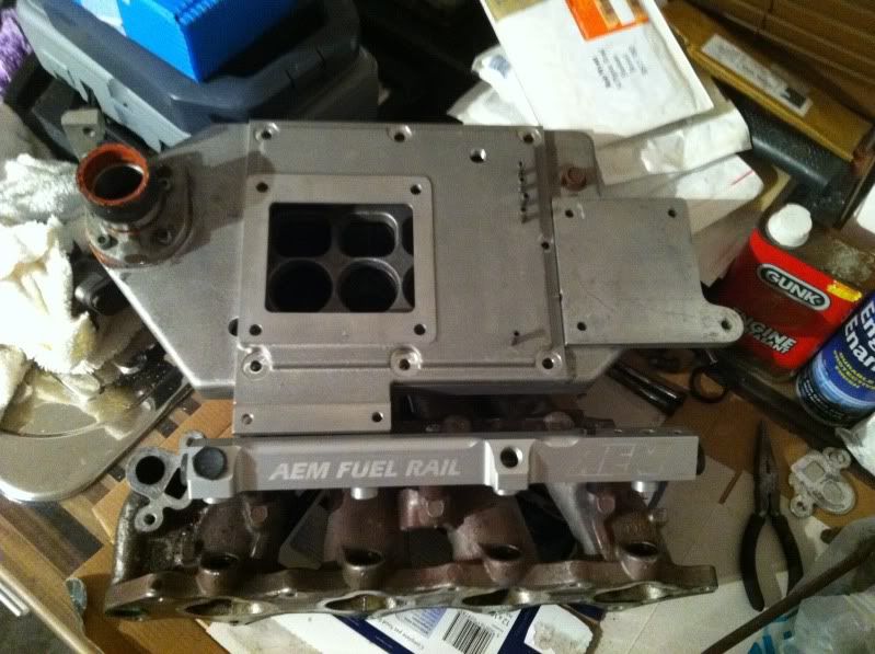
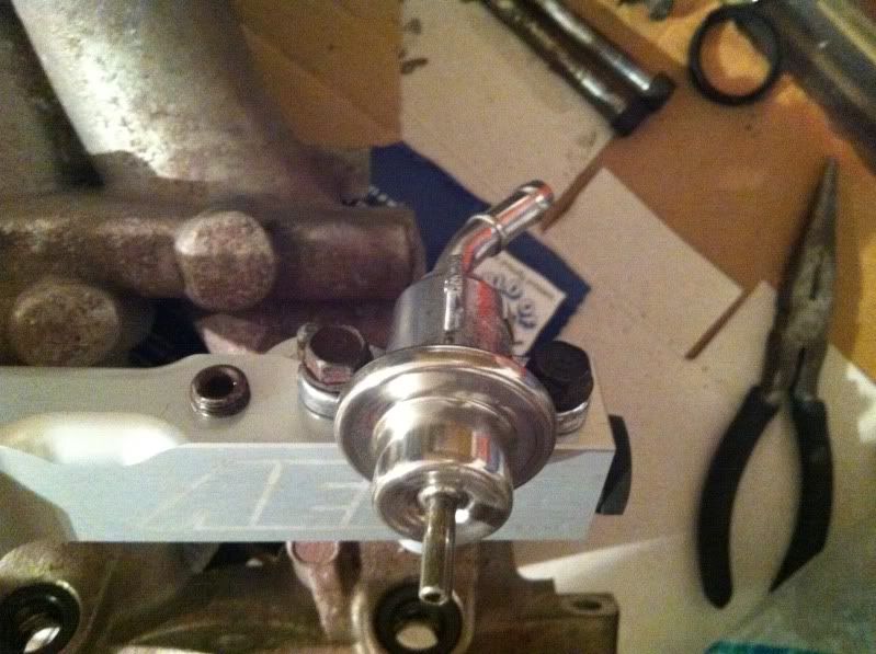
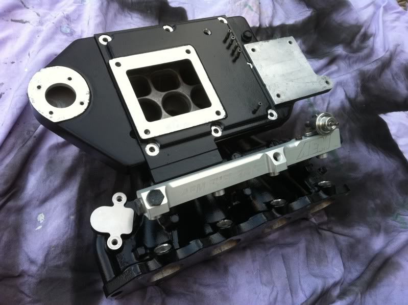
Then I added my new polished up OEM 1:1 linear fuel pressure regulator:
And then my EGR plate just laid loose:
All looking good – but it’s all very dusty and dirty and I have a general colour scheme in mind for the engine now = BLACK and SILVER. So I dismantled it all and started on the intake manifold first.
I removed the injector seals, and below this some plastic spacers, just gently prise them out with a flat head screwdriver:
Also I didn’t take a pic, but the Intake Air Temp Sensor is fixed to the passenger side of the lower intake manifold – small white plastic thing removed via 2 posi screws.
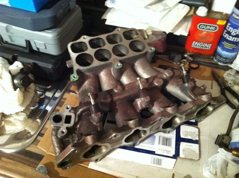
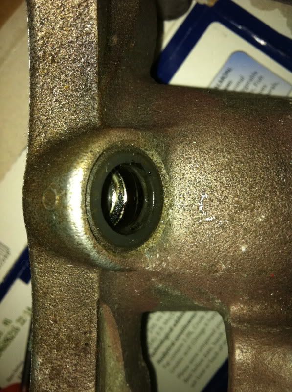
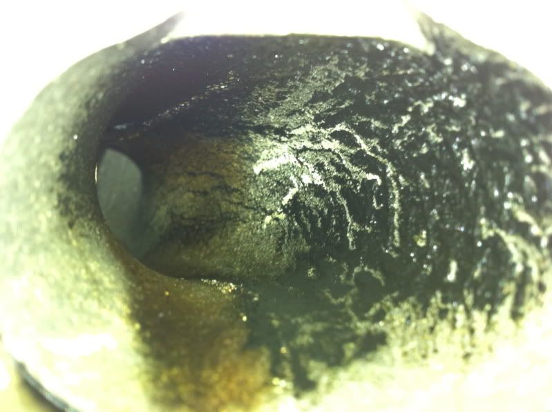
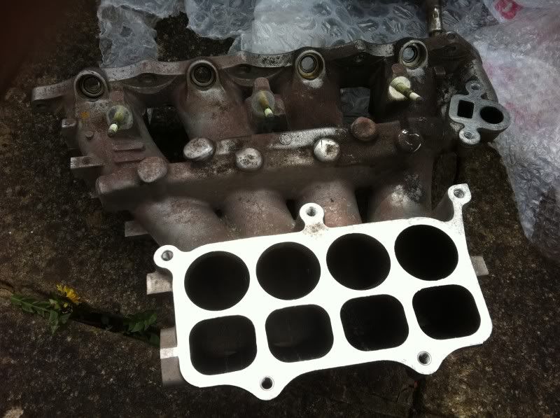
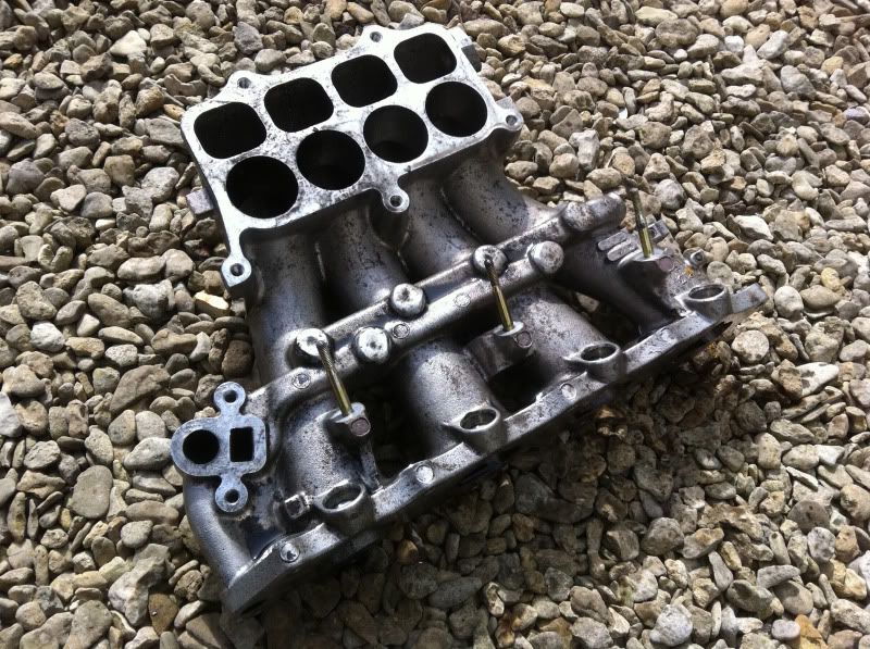
So it was a bare metal intake left, albeit with the brass studs for the fuel rail. Let’s see how much gunk can build up over time in the intake runners shall we:
Looking from the engine side, Port 1:
Port 2
Port 3
Port 4
Now from the top looking down from the IAB plate / top plenum:
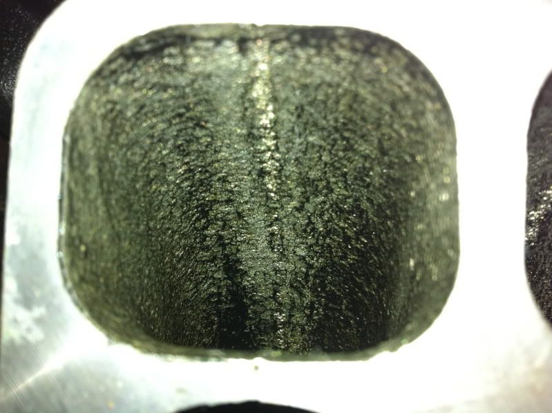
Conclusion = Gunked Up!
This is why I now hate EGR, PCV and Evap Emssions systems. I don’t care how much I reduce my emissions or how much extra mpg I get, that crap is not worth it for the life of the engine.
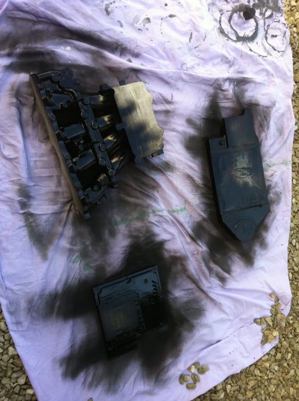
Right so, roll on to a fairly nice weekend day where I could get cleaning and painting and I started with this:
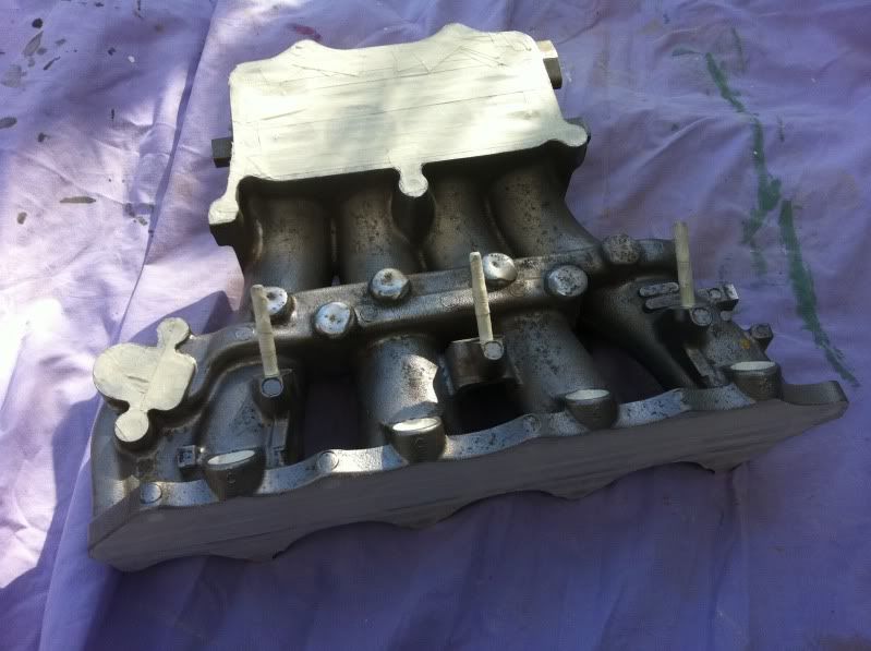
After a good soak and scrub using GUNK engine degreaser, I had it looking like this:
A little improvement, but there were marks and such all over it. So I masked it up – this took some time to do accurately, but I would say the finish is in the prep, so I took my time:
Now to add some BLACK!
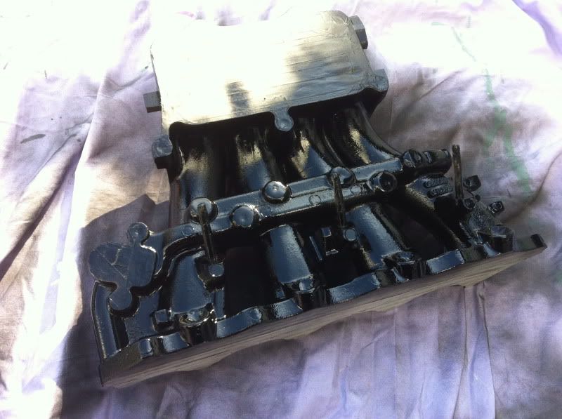
I wanted something in black, but also something that would take easily enough to the cast metal and also withstand some high temperatures, because as explained previously, the Eaton supercharger without a method of cooling heats up intake air the more it is compressed – especially at 9psi+. So Engine Enamel seemed perfect! I needed some for the block anyway.

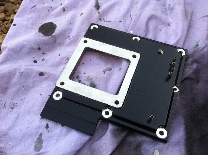
The JRSC mounting plate got the same treatment, although being a new item was already spotlessly clean:

Now for the JRSC main plenum. I removed the bypass valve, see more of the instant gasket yet to remove before masking. Also took some better pics of the bypass valve:
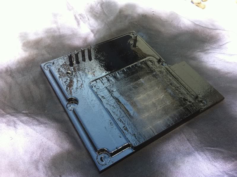
Before you knew it, that was masked up and sprayed too, all in the same gloss black engine enamel:
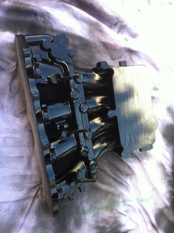
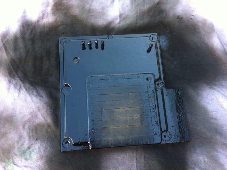
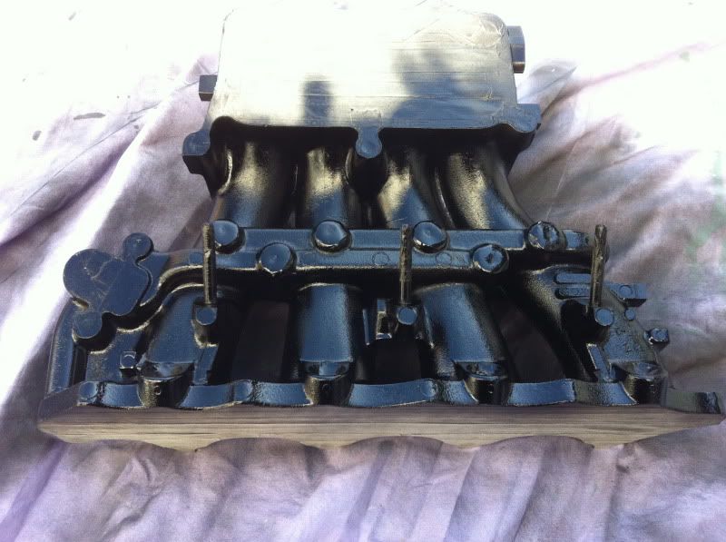
A short while later it was touch dry to start removing the masking to see how well this idea was gonna work. Ta da!
Mmm…fresh! A little spray had creeped under some masking here and there, but I go over with a razor blade gasket scraper later to give a clean finish.
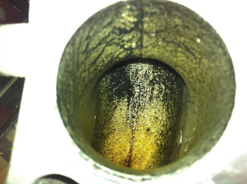
So how well did my GUNK clean of the runners do? See for youself:
From the top:
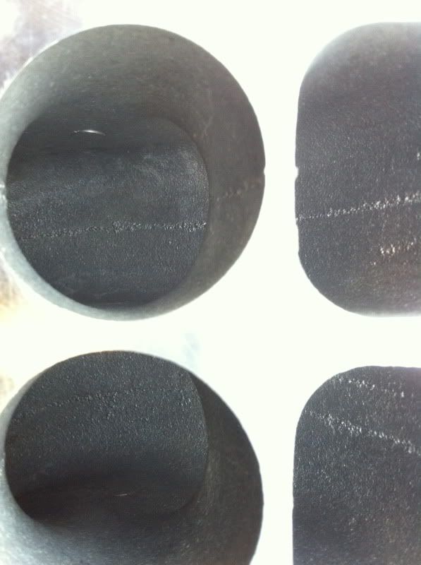
Port 1
Port 2
Port 3
Port 4
Loads better!
This shows you the horrible casting marks that I plan to remove as part of the mild port and polish of the intake and parts.
Careful masking of the brass fuel rail studs and the injector seal seats were rewarded:
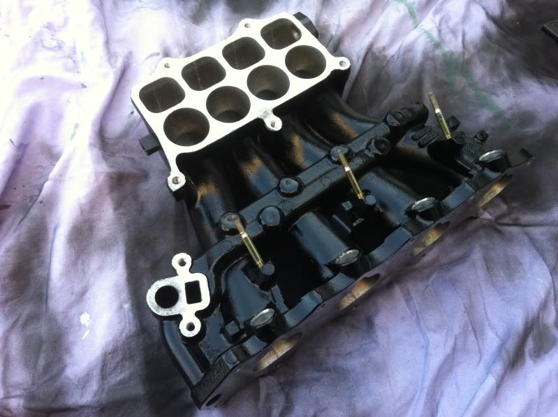
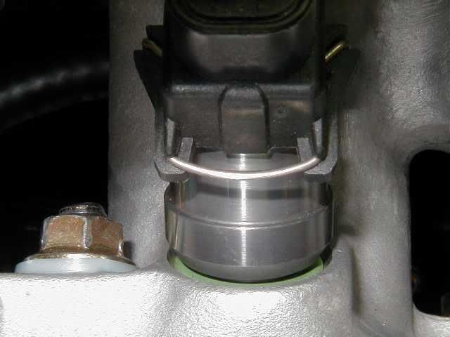
Now to unveil the JRSC mount plate:
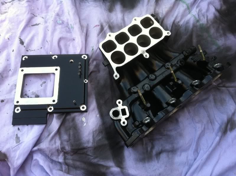
And finally the plenum joined the party and I pieced it together to get an overall picture of how it would look:
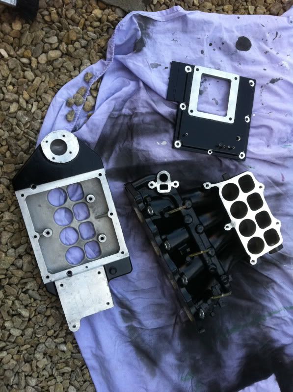


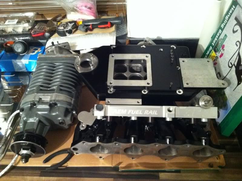
Ooh!!! Looked sweet, I ran to get the other bits to install on it and see the contrast of the black against silver/metallic objects:
Awesome! Turned out better than I had hoped!
After cleaning up the small overspray with a gasket scraper I took it inside again and found a little friend for it all – oh, hello Mr. Boost!

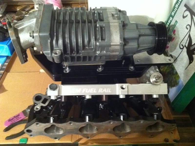
Well that was enough work to keep me very motivated for the coming weeks. Almost like the polishing of a crown before crowning a King!
Injector Seals
Since that day, I have worked on the injector seals and resistor box a little to enable me to fit the larger 550cc RC saturated injectors over the 4th gens OEM 345cc peak and hold injectors.
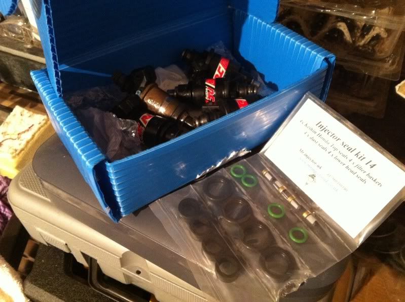
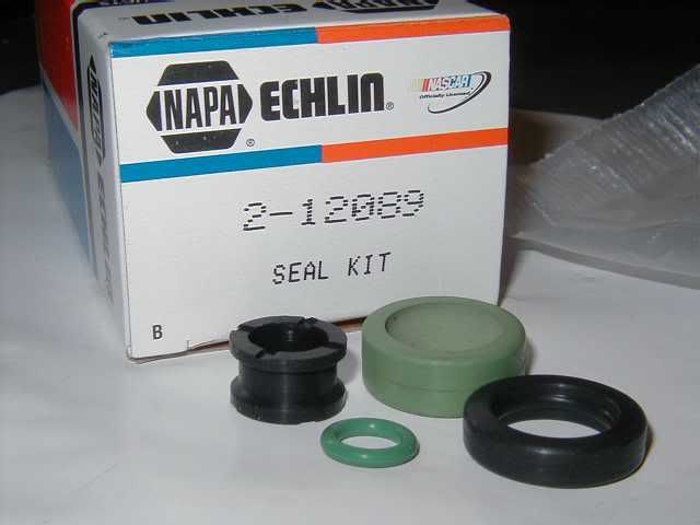
First off was to tackle the seals. I bought a new seal kit from Mr Injector UK – good seller.

These were about £20 posted and came with:
- 4 new top O-ring seals (green) to fit onto the top of the injector and seal against the fuel rail ports.
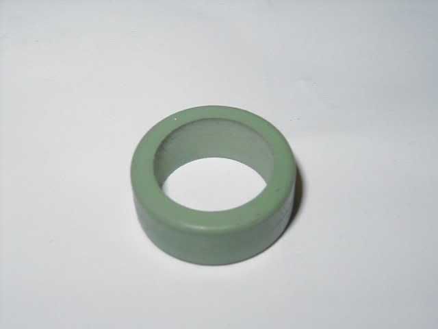
- 4 new rubber seals (black – third line of the pouch down) which seal the injector against the intake manifold as removed earlier
- 4 new plastic spacers to fit onto the top of the injector before the O-ring groove, these just sit the fuel rail into the right level position across all injectors
- 4 new basket filters – these normally replace the small filters in the top of the injector which avoid any micro debris getting into the injector. However I can’t use these as they don’t seem to fit the RC’s, which I also can’t seem to remove. The existing RC ones look ok anyway.
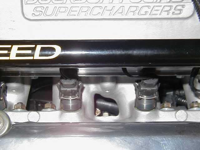
Here they are, with my box of injectors:
Here is the original fuel rail and OEM injectors still in place:
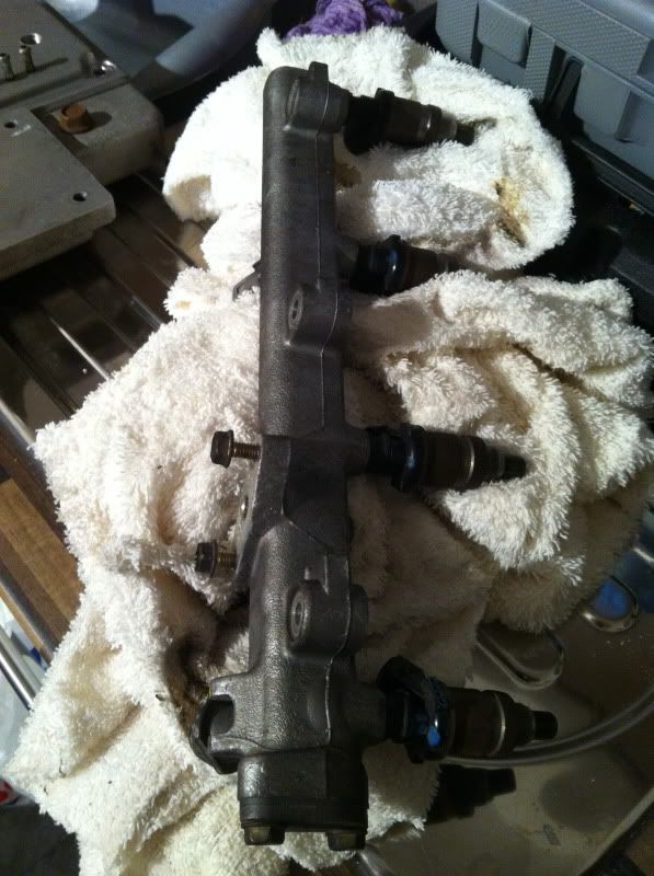
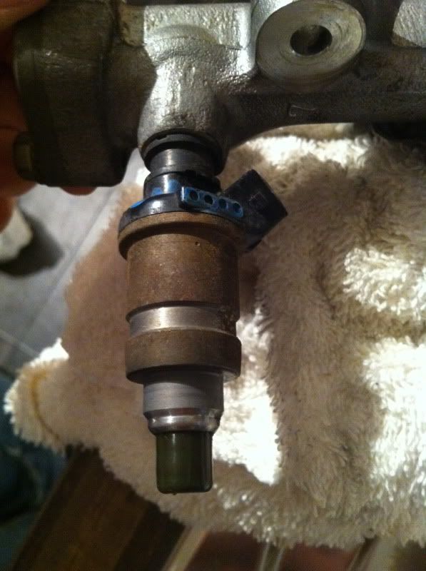
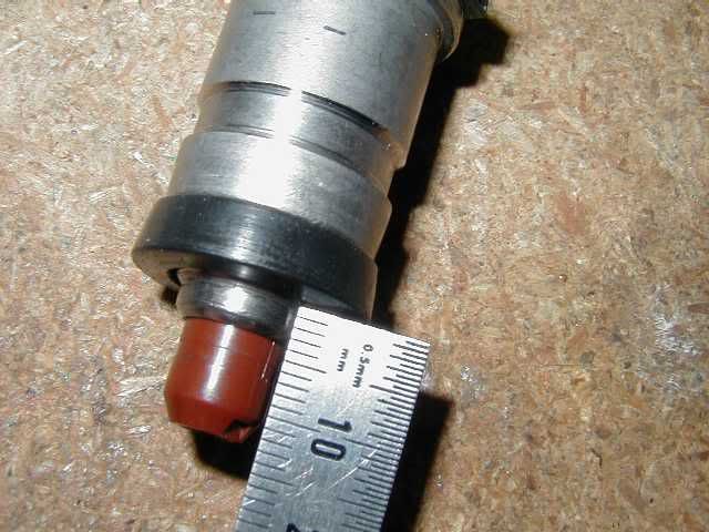
Removing the injectors and laying them up side by side with the new ones to compare:
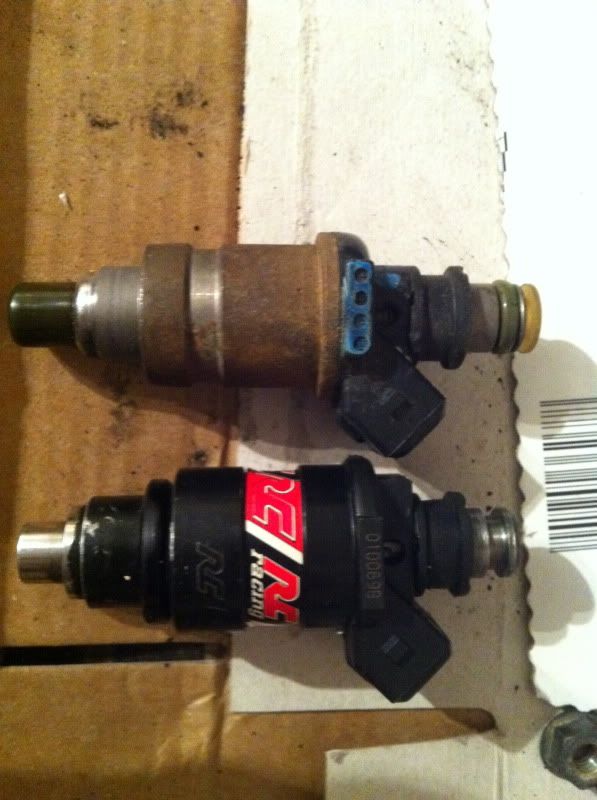
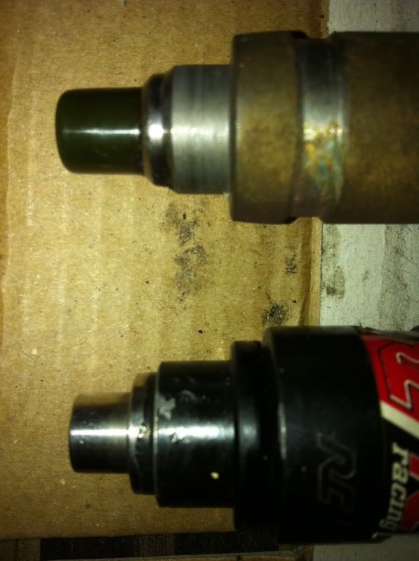
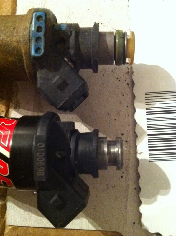
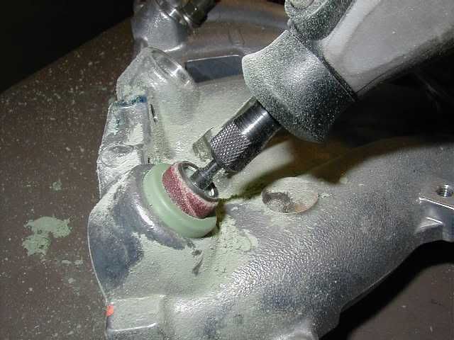
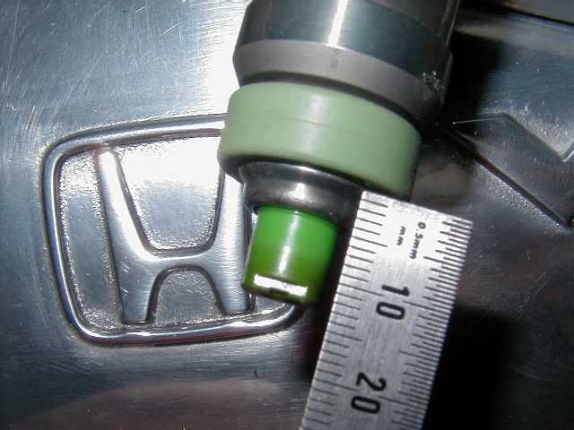
Overall the RC injectors are fractionally shorter in total length, but this gets lost in the fuel rail port anyway. But the main issue with the RC injectors is the opening in the seal to the intake manifold to take the injector is too small. You can see in the second pic that the RC’s lower part is slightly wider. The solution? Enlarge the hole in the seal using a dremel / rotary type tool. This seemed easy enough, but the reality was it takes some time and some patience to get a nice smooth enlarged opening. I’ve actually still got a couple to do but here’s when I started:
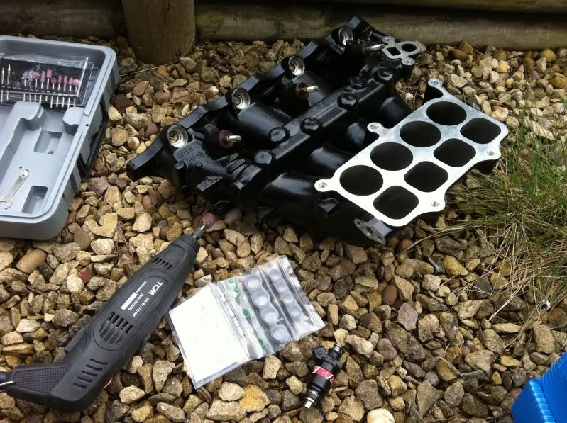
And some pics of the process taken from an old how-to write up – unfortunately the link doesn’t work anymore:
So that’s issue one sorted out.
Next up was the injector resistor box. If you remember my write up earlier on in my build where I discussed fuelling and the difference in injector types? Well to recap, the RC injectors I have are a high impedance saturated type injector, normally required for most other Honda’s – Civics, 5th gen Prelude, etc. This is because they came off of a 5th gen Prelude JRSC kit.
However, the 4th gen Prelude runs a low impedance peak and hold type injector, which in comparison is a better design and can manage larger cc’s of fuel (550+). But at £300+ for a set of RC’s I stuck with these and looked for the workaround. The 4th gens peak and hold have a large resistor box which lowers the voltage returned to the injector drivers in the ECU. Without running this resistor box, you stand a good chance of frying these drivers in the ECU. That’s why most H22 powered Civics like to get ahold of them!
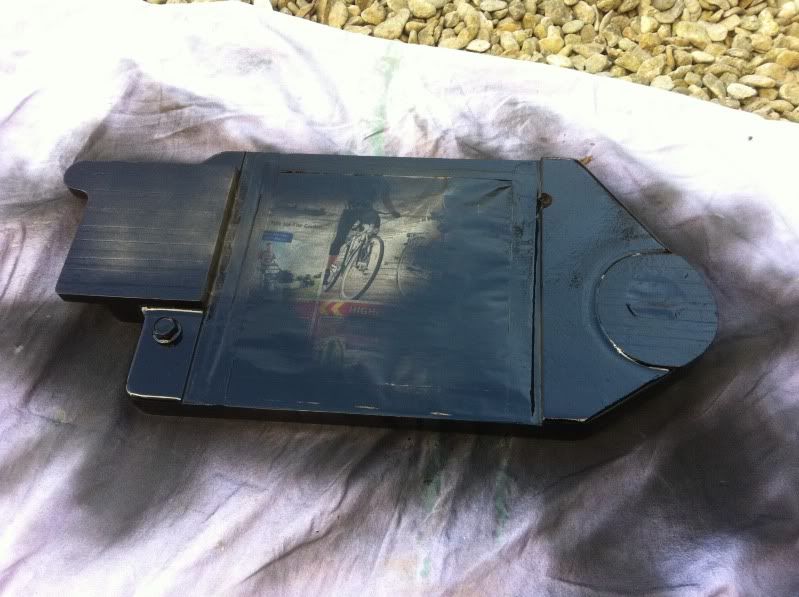
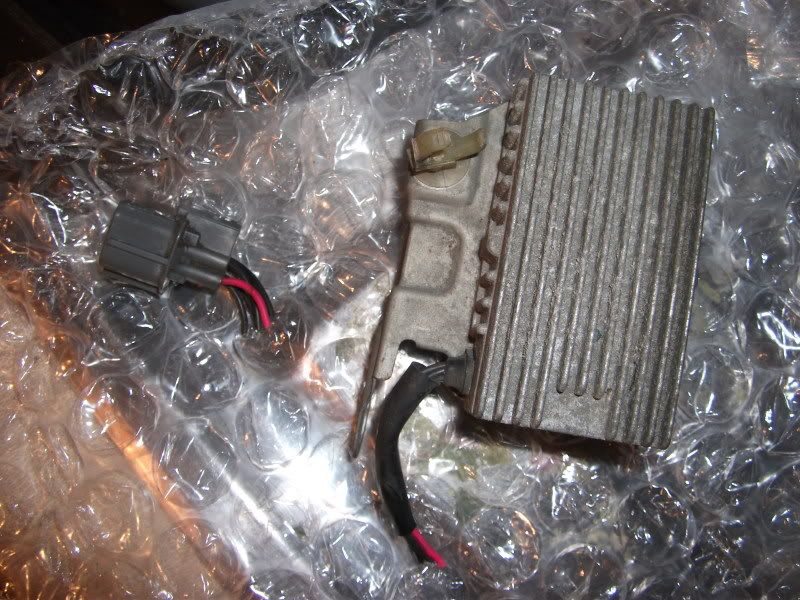
Here is the little blighter:
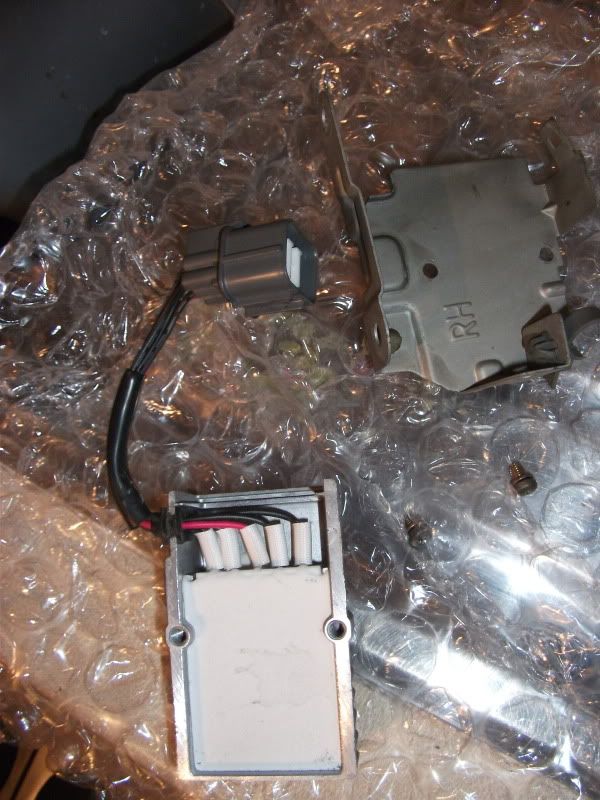
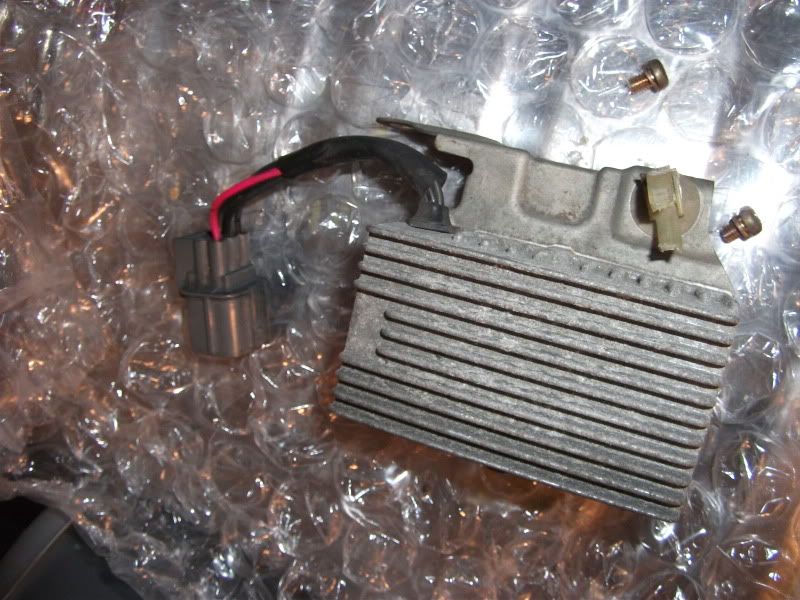
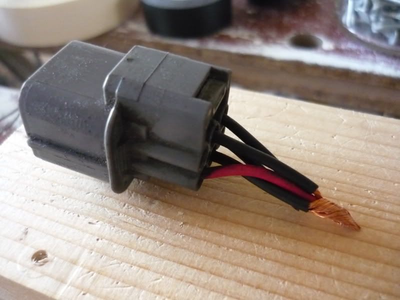
The solution is simply to remove the resistor pack from the circuit and it will be wired up nearly the same as a 5th gen. I bought a spare resistor box and simply cut the electrical connector off with about an inch or so of wiring. Luckily I sold the box on to a H22 Civic because they have to cut and splice this in – WIN/WIN.
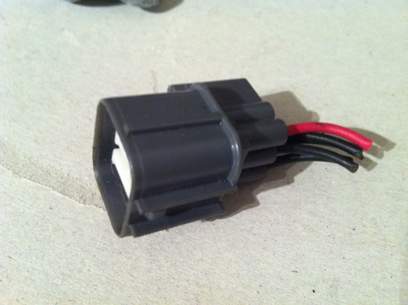
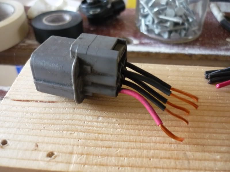
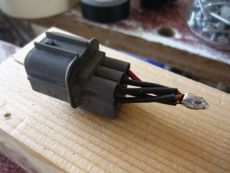
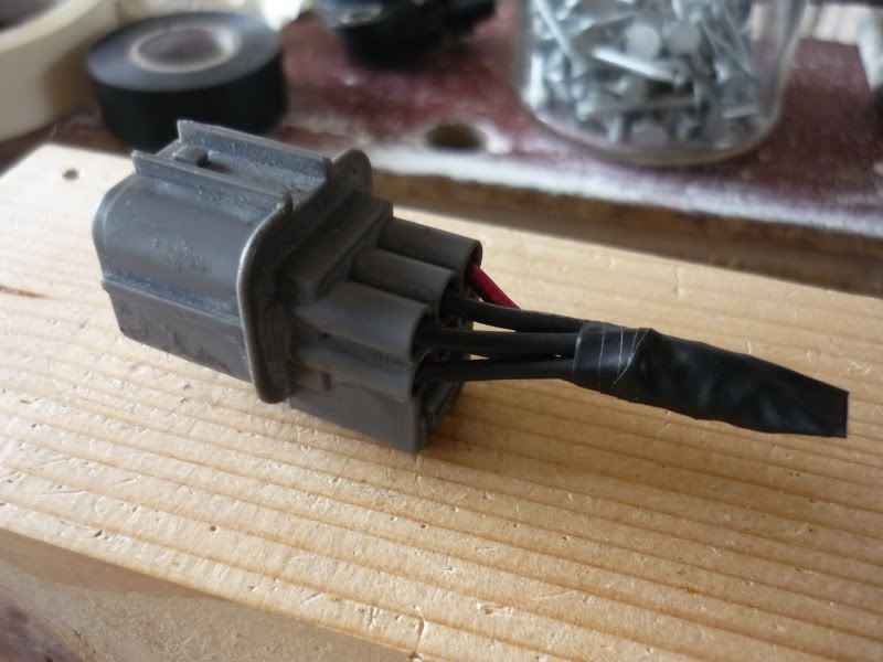
The plug has 4 black wires and one red. Just trim back the plastic shielding and solder them all together and tape it up:
I realise I havn’t taken any pics of the soldering, etc. So shamelessly stolen from Nathan’s thread for completeness – it’s basically the same as this (Cheers Nathan – sure you won’t mind?):
The injector resistor pack is bolted to the top of the firewall next to the brake booster and wiper relay, I’ll point it out again later in the updates when I removed it (and the relay) and relocated the wiring.
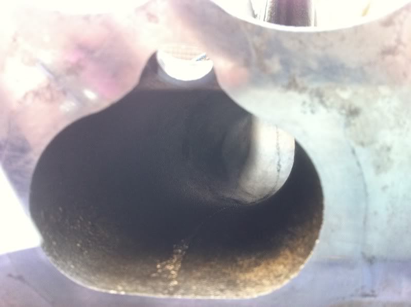
Eaton M62 Supercharger Inspection
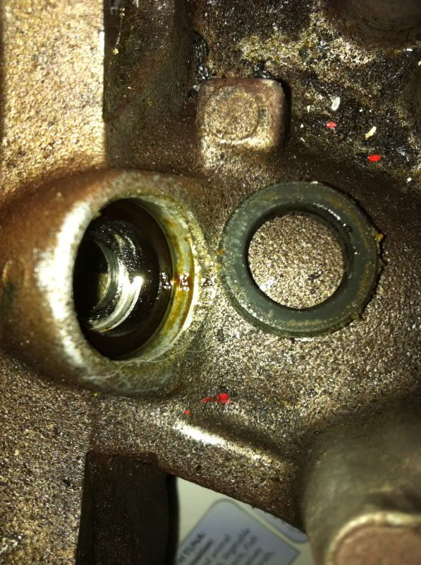
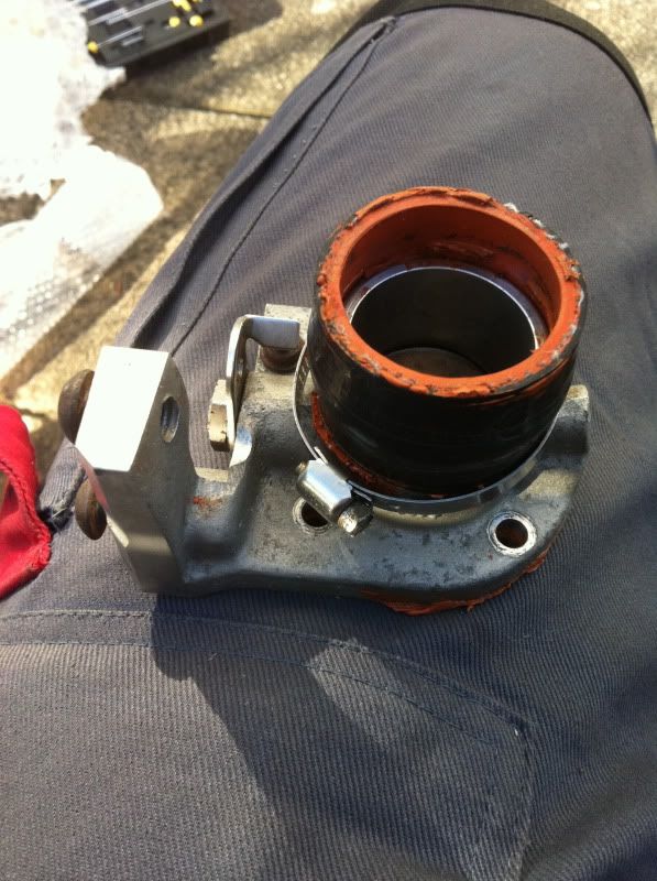
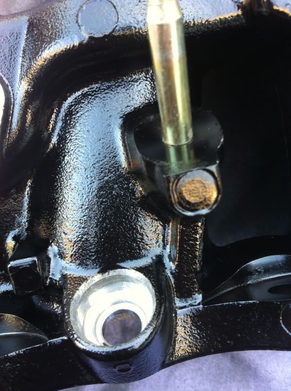
I needed to remove the JRSC inlet pipe to most likely give it a lick of paint too, but I wanted to inspect the condition of the rotors to see how good the SC is. This is looking at the bottom of the ‘boost’ side if you will:
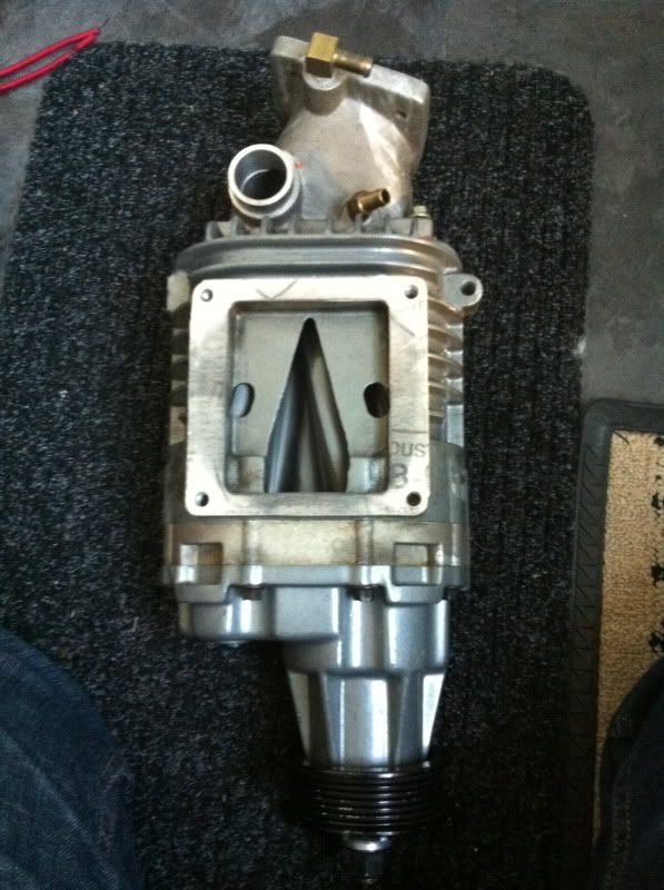
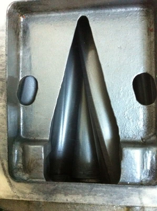
Two things to check here while rotating the pulley/rotors by hand, one is to check that any of the teflon coating of the rotors hasn’t started to flake off – not good to push into your engine’s combustion chambers. Secondly is to check for any scoring on the edge of the rotors fins. Mine seemed in good condition, with no sign of flaking and only light touches, but no deep scoring to the fins. Not bad for a second hand supercharger, I wonder what the mileage is on it?
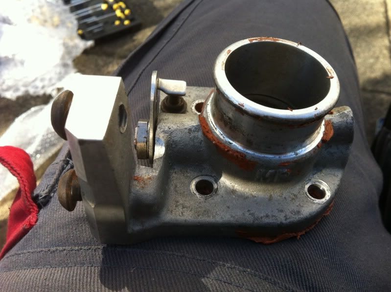
So next up remove the inlet pipe – notice more instant gasket!

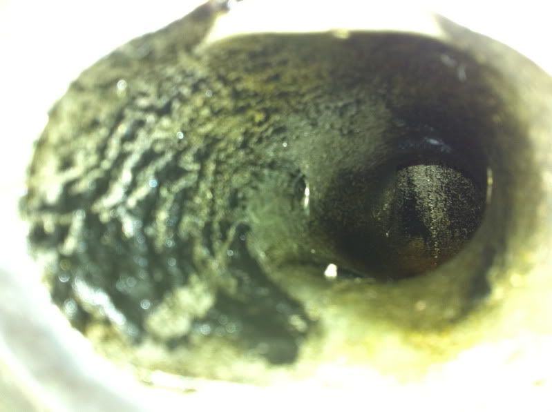
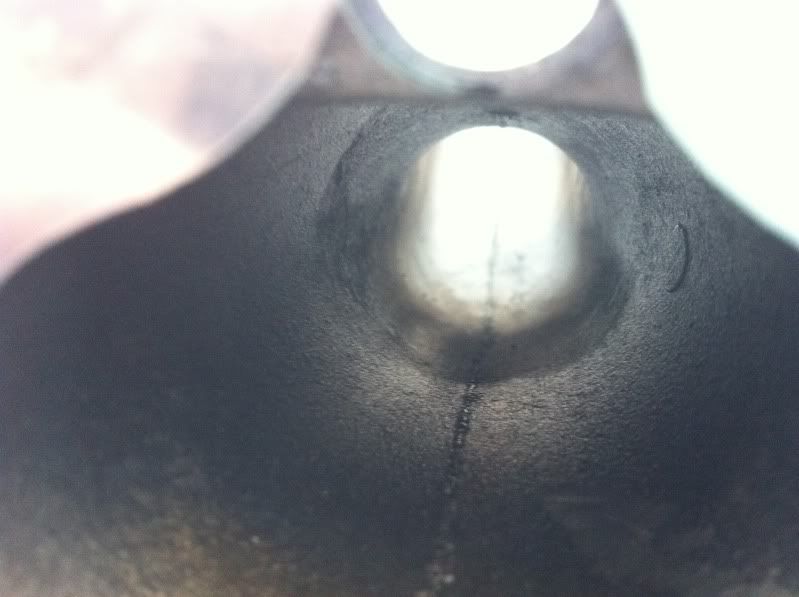
Now to check the end of the rotors for any scoring too:
Looks not too bad:
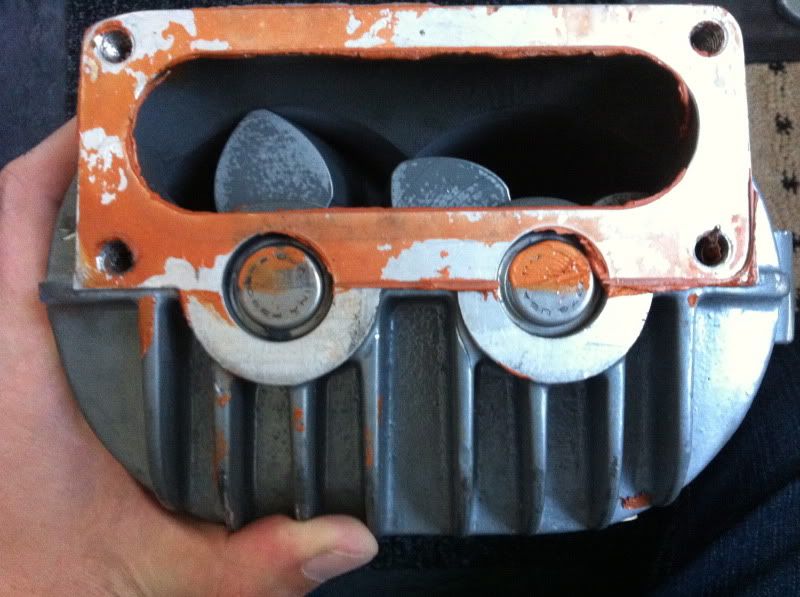
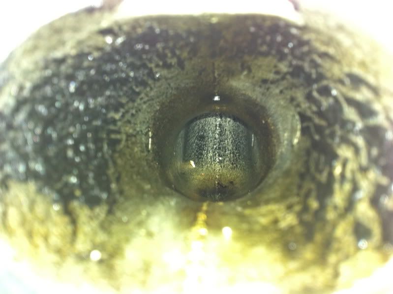
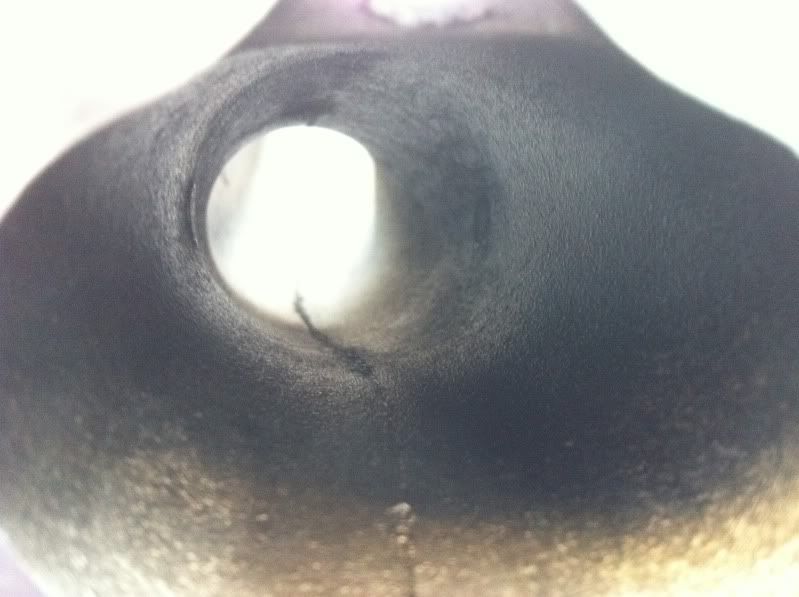
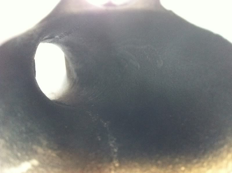
Let’s get closer for a better look:
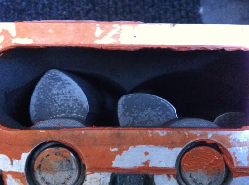
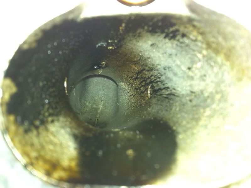
Some scoring has started – not ideal but I’ve seen worse.
The reason for the scoring is wear on the bearings that hold the rotors in place. As they wear over time the bearing creates a little play which allows the rotors to touch the casing ever so slightly – the tolerances in roots chargers are very tight indeed.
I’m not going to worry about it too much at the moment, but after I’ve put some miles on it, it’ll need a rebuild. A rebuild, will normally replace bearings, couplers and oil in the sealed end case, but I’ll also plan to strip the Teflon coating, have the rotors and casings machine smooth, no doubt widen inlet and outlet and port and polish it all to get more airflow – it’s a popular mod in the states to decrease boost but gain more power! WIN/WIN again!

That’s it for this update. Next time, we go back into the garage to remove more parts!
I bet you are all just wanting to see the updates where I’m fitting new bits to the car not just removing and tarting bits up?
Cheers,
Rob