
Congratulations to vtecmec for winning May/June's Lude Of The Month, with his DIY Turbo BB1 build.
>>> Click Here For Profile <<<

>>> Click Here For Profile <<<
S2000 starter button wiring diagram
-
W1ggz

- Posts: 2524
- Joined: Sun Jul 22, 2012 3:10 pm
- My Generation: 4G
- PSN GamerTag: W1GGZ
- Location: Portishead nr Bristol
- Contact:
S2000 starter button wiring diagram
My old Lude had the engine start on the alarm fob. Where I worked in Portishead all the school kids would hang around by the shop next to my car and if I saw someone lean on it id start it up used to scare the crap out of them.
-
wurlycorner

- Ye are glad to be dead, RIGHT?
- Posts: 21224
- Joined: Sat May 19, 2012 3:33 pm
- My Generation: 4G
- Location: Chelmsford, Essex
- Has thanked: 1968 times
- Been thanked: 240 times
-
W1ggz
- Posts: 2524
- Joined: Sun Jul 22, 2012 3:10 pm
- My Generation: 4G
- PSN GamerTag: W1GGZ
- Location: Portishead nr Bristol
- Contact:
Re: S2000 starter button wiring diagram
Sorry dude this was in my old 2.3 from 7 years ago was a Clifford alarm system that cost me £800
-
Drax

- Moderator
- Posts: 6268
- Joined: Wed Dec 22, 2010 4:05 pm
- My Generation: 4G
- Location: Wrexham, North Wales
- Has thanked: 16 times
- Been thanked: 381 times
I know thisalinton wrote:If you fit a start button, it's annoying to have to put the key in and turn it to the ignition position. You might as well start the car with the key then!
still no answer about the original question though sadly....
2.2 JDM DOHC SI-VTEC LSD TCS 4WS ABS BB1 MANUAL 1992

FOR PAUL
FOR PAUL
-
Drax
- Moderator
- Posts: 6268
- Joined: Wed Dec 22, 2010 4:05 pm
- My Generation: 4G
- Location: Wrexham, North Wales
- Has thanked: 16 times
- Been thanked: 381 times
bump! anyone able to answer this?Drax wrote:Im thick.Kawa wrote:
do I interpret this as plug one of the wires from the starter button to the + for the cigarette lighter, and the other wire from the button to a relay (what relay, and bought from where?) and then wire that into the same + to the cigarette lighter, the ignition white cable and the ignition black&white cable.......?
thank you!
2.2 JDM DOHC SI-VTEC LSD TCS 4WS ABS BB1 MANUAL 1992
FOR PAUL
FOR PAUL
-
wurlycorner
- Ye are glad to be dead, RIGHT?
- Posts: 21224
- Joined: Sat May 19, 2012 3:33 pm
- My Generation: 4G
- Location: Chelmsford, Essex
- Has thanked: 1968 times
- Been thanked: 240 times
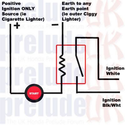
The relay will have 4 terminals.
2 terminals will be for the coil (one either side of the coil)
2 terminal will be for the switch (one either side of the switch)
It should show on the relay a picture of the internal circuit, with the terminals numbered/labelled accordingly.
Wire one side of the Starter button to the positive terminal for the fag lighter.
Wire the other side of the starter button to one side of the coil on the relay (e.g. 85)
Wire the other side of the coil on the relay (e.g. 86) to earth (somewhere good on the chassis locally to the fag lighter, or use the existing fag lighter earth)
Take the ignition white wire and wire that to one side of the relay switch (it doesn't really matter which, but good practise would dictate the side shown as 'normally closed' e.g. 30)
Take the ignition black/white wire and wire that the other side of the relay switch (e.g. 87)
Voila!
As for the relay, any automotive 12v normally open 4 pin relay would do that you can get your hands on with a corresponding base to allow you to wire to (or just use insulated spade connectors the right size).
I don't know what current that circuit draws, but if you just pick a nice high current rated relay you'll be fine.
This would do;
http://www.halfords.com/motoring/garage ... -40a-4-pin
The pin numbers I've mentioned above relate to the circuit diagram for that relay, which is a very common relay internal layout.
EDIT: Halfords are crap and don't do relay bases It doesn't matter, because you can always just use standard spade terminals to go directly onto the bottom of the relay. Relay bases are just neater, so it's up to you.
Here's a similar relay complete with base;
http://www.ebay.co.uk/itm/12V-4-Pin-40- ... 1417674825
You'll find it a bit more fiddly wiring into those spade terminals though, because they don't work with an 'ordinary' crimp tool, so it's all up to what you prefer/are comfortable with/can be arsed to spend your time doing
2 terminals will be for the coil (one either side of the coil)
2 terminal will be for the switch (one either side of the switch)
It should show on the relay a picture of the internal circuit, with the terminals numbered/labelled accordingly.
Wire one side of the Starter button to the positive terminal for the fag lighter.
Wire the other side of the starter button to one side of the coil on the relay (e.g. 85)
Wire the other side of the coil on the relay (e.g. 86) to earth (somewhere good on the chassis locally to the fag lighter, or use the existing fag lighter earth)
Take the ignition white wire and wire that to one side of the relay switch (it doesn't really matter which, but good practise would dictate the side shown as 'normally closed' e.g. 30)
Take the ignition black/white wire and wire that the other side of the relay switch (e.g. 87)
Voila!
As for the relay, any automotive 12v normally open 4 pin relay would do that you can get your hands on with a corresponding base to allow you to wire to (or just use insulated spade connectors the right size).
I don't know what current that circuit draws, but if you just pick a nice high current rated relay you'll be fine.
This would do;
http://www.halfords.com/motoring/garage ... -40a-4-pin
The pin numbers I've mentioned above relate to the circuit diagram for that relay, which is a very common relay internal layout.
EDIT: Halfords are crap and don't do relay bases
Here's a similar relay complete with base;
http://www.ebay.co.uk/itm/12V-4-Pin-40- ... 1417674825
You'll find it a bit more fiddly wiring into those spade terminals though, because they don't work with an 'ordinary' crimp tool, so it's all up to what you prefer/are comfortable with/can be arsed to spend your time doing
--
Iain.
Iain.
Super Secret 1G (not really super secret!)
-
jjmartin349571

- Supporter 2016
- Posts: 3344
- Joined: Fri Feb 10, 2012 12:41 am
- My Generation: 4G
- XBOX GamerTag: jjm349571
- Location: Newhaven, East Sussex
- Contact:
FWIW Halford's sell a version of that relay made by Ring, they keep it with the fog light kits and for some reason it's only £2-3 compared to the price of the Halford's own version. I used one for the power window install on my Golf amongst other bits of wiring and they seem to be perfectly up to the job.
I've always used insulated spade terminals on these, but Iain is right it does make the job look bloody messy. Although once the trim is back on nobody knows what lies beneath
I've always used insulated spade terminals on these, but Iain is right it does make the job look bloody messy. Although once the trim is back on nobody knows what lies beneath