Congratulations to vtecmec for winning May/June's Lude Of The Month, with his DIY Turbo BB1 build.

>>> Click Here For Profile <<<

Image

Prelude Remapped chips-JDM Spoon V2 Auto/Manual+UKDM+Chrome+

Got some things for sale? Put them in this section
User avatar
wurlycorner
Ye are glad to be dead, RIGHT?
Posts: 21493
Joined: Sat May 19, 2012 3:33 pm
My Generation: 4G
Location: Chelmsford, Essex
Has thanked: 2481 times
Been thanked: 306 times

Post by wurlycorner » Wed Sep 11, 2013 2:56 pm

Over the last few days I've finally got round to installing a 'Rob' chip into an ECU. Haven't fitted it to the car yet (tonight :scaredtoss: ) but it's ready to go.
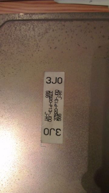
Rob, FYI this was Kris (Edu's) original 4 pin ECU and the chip you sold him (he bought a 3-pin ready chipped ECU and stuck that in instead).
Image

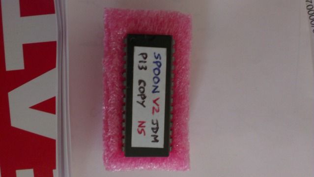
I still haven't got round to doing anything with the chip I bought off you about 3 years ago for my UKDM :facepalm:
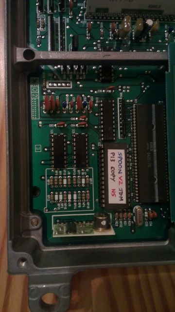
Nb: the large code on the chip is the wrong kind (not C3) but I decided to try it anyway :? If not, then I've been a 4thgenphil and ruined my solution to getting TCS working again, but hey-ho...
EDIT: :lol: :lol: at the swear filter :D I didn't actually write 4thgenphil... :lol:

Robs instructions are very good, but I took the opportunity to take a few pics so here's my guide. Rob, if I've :spammed: the drokk out of your thread :oops: just delete it!!! :bat:

I'll add to comments from others that installing it yourself isn't the easiest job in the world - I was trained in soldering/electronics at college and am quite experienced (for a DIY'er) but I also had a mate help who's apprentice trained/qualified elecronics technician and spent 15 years repairing electronic equipment and it certainly wasn't the easiest job either of us have done. If you're not confident and PATIENT, follow Rob's advice and get an electronics repairer (or bluejackhustler) to do it for you.

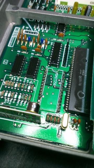
Looking at the old chip;
Image

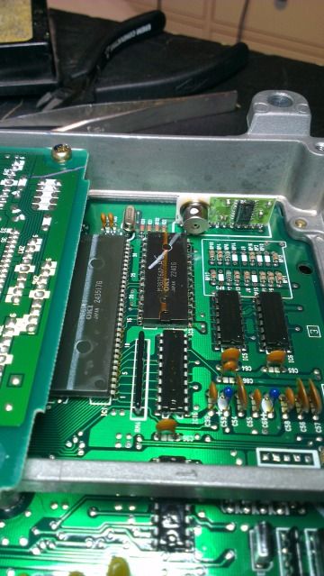
Tried to get the old chip out in one go (to keep as a spare) by unsoldering, but the board is very (comparitively) thick so drawing the solder out completely from inside the holes/the other side of the boards just wasn't happening. Others have done it, maybe we were particularly unlucky with this ECU, who knows, but either way, the chip made what LLL would describe as a one way trip;
Image
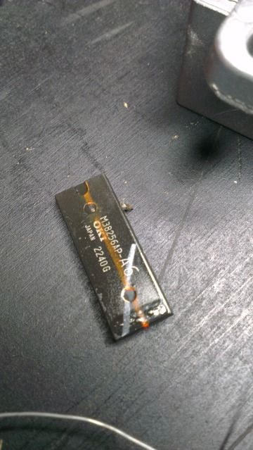
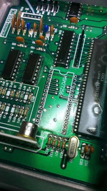
Which left the legs in the board;
Image

If you're going this method, you need small and very sharp/strong side cutters. Do it before trying to de-solder the back of the pins first, because it means they're securely held in and unlikely to damage the board/track pads while cutting (it's quite a violent shock when they cleave). The pins are then really easy to unsolder and remove (use tweezers to lift them out).

You then need to clean up the pads properly and clean out the holes, which takes a long time and you need patience! The pads are small so need to be careful not to overheat them, which could damage or cause them to lift off;
Image

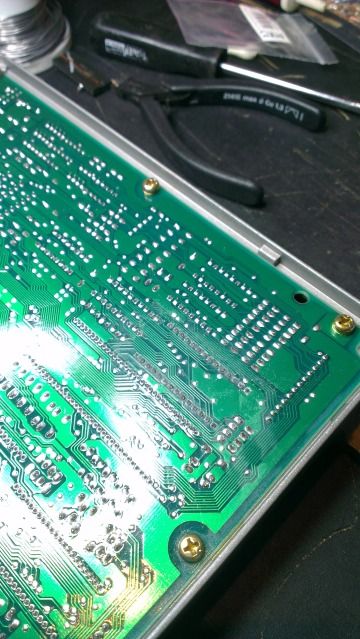
NB: We found (much to my distain) that solder suckers aren't any good for any of this job, you need de-solder braid/wick.

The PCB in the ECU is heavily lacquered (for strength and to cope with the moisture/vibration that you get in a car) so after all the solder is clear, clean everything off to remove flux/lacquer/other crap with electro-clean and a decent rag or cotton bud that won't leave fibres everywhere. Be gentle though, so as not to damage any tracks.

Then you can insert the new holder and re-solder on the back. As it's a multi-layer board, you need to make sure that enough solder is applied so that it runs properly through the hole to the other side, but don't overload it.
Image
Image

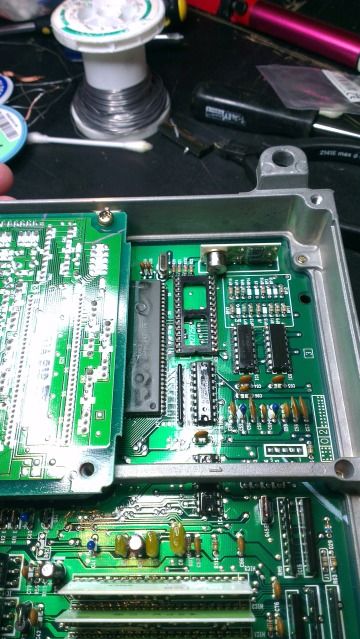
Note in the second pic that on my ECU, the small ancilliary PCB that mounts vertically at the end of our chip was leant forward slightly and overhung the end of the socket. There was no way that the new chip would fit into the socket (overlap was about 2mm :roll: ). If you have this problem, don't be tempted to try and bend that other board backwards to get the clearance - it WILL break. Yep, you've guessed it, de-solder it on the back and then you run the soldering iron up and down the pins until the solder becomes molten on the top of the board and then you can gently tip it back. Don't overheat it or you'll damage the ancilliary PCB and only move it as far as is needed, no further. Then re-solder the back of it, and away you go.
Not all ECU's have this style of ancilliary board - some have a 'potted' board from what I can make out, and they don't overhang, so you may get lucky.

Image

After everything is finished, clean off again to remove any flux from the solder and then you can relacquer (available from Maplins, about £4). Don't have to, but it's advisable. Avoid spraying lacquer onto the top of the chip/legs though.

bluejackhustler
Supporter 2014
Posts: 172
Joined: Tue Jul 12, 2011 9:30 pm
My Generation: 4G
PSN GamerTag: vtecmoggy
Location: North Shropshire
Has thanked: 1 time
Been thanked: 2 times

Post by bluejackhustler » Wed Sep 11, 2013 7:09 pm

All good advice but, a professional can remove the original OKI chip without damage.

Each one I've done has had the original returned.
Last edited by bluejackhustler on Wed Sep 11, 2013 9:23 pm, edited 1 time in total.

User avatar
wurlycorner
Ye are glad to be dead, RIGHT?
Posts: 21493
Joined: Sat May 19, 2012 3:33 pm
My Generation: 4G
Location: Chelmsford, Essex
Has thanked: 2481 times
Been thanked: 306 times

Post by wurlycorner » Wed Sep 11, 2013 7:29 pm

Yep, like I say we both knew that was possible and we were just unlucky not being able to get the solder fully out in the time we had - didn't have very good quality braid (so the flux in it wasn't great) but tbh the main problem was that we were really running out of time and needed to make sure we had enough time to clean it all up after the chip was out (can't short cut that bit).

So long as it works I'm not at all bothered, because I wouldn't plan on ever converting back. If it doesn't, well then I'll either be in the market for a replacement Oki chip or soldering legs back onto the one I have :lol:


I forgot to add that a magnifying lamp combo helps massively to check for any damage to the pads after/during removal.


EDIT:
:hurr:

Well it hasn't made it off the drive yet so I'll need to give it a run tomorrow, but started up, warmed up and revs fine on the drive with no CEL, so looks like the chips work in ECU's with this on the front;
Image
And A6 on the Oki chip.

Actually, re-reading the first post, does the C3 only matter for the UKDM chip anyway? :?
Last edited by wurlycorner on Wed Sep 11, 2013 9:31 pm, edited 2 times in total.

User avatar
David.slough
Posts: 148
Joined: Sun Jan 22, 2012 6:24 pm
My Generation: 4G

Re: Prelude Remapped chips-JDM Spoon V2 Auto/Manual+UKDM+Chr

Post by David.slough » Wed Sep 11, 2013 9:16 pm

Payment sent, pm sent and posted here :) I like to cover every angle :)
Proud owner of a 4th Gen BB4
序曲 Prelude to War

User avatar
bb1boy
Posts: 4459
Joined: Mon Jan 30, 2012 11:57 am
My Generation: 4G
XBOX GamerTag: adam fantastic

Post by bb1boy » Thu Sep 12, 2013 9:43 am

How much are these chips? I have a socketed ECU already.
Image

User avatar
nucleustylzlude
Moderator
Posts: 4013
Joined: Wed Aug 11, 2010 11:46 pm
My Generation: 4G
Location: Bristol, UK!
Been thanked: 7 times
Contact:

Post by nucleustylzlude » Thu Sep 12, 2013 3:55 pm

Thanks Iain, some good pics there showing the cut pin method. Let me know how you get on once its fitted. :D

A6 or A3 I don't think makes a difference on the JDMs that I've come across. Its only the UK/European ECUs that end with the code G00 & G01 (the sticker on the ECU, not the OKI chip reference) that are different codesets apparently. JDM's all seem to work from the tons of chips I've shipped out to people - J00, J01, N00, N01.

The ECU you have are the JDM only small square type, which adds the secondary board in one corner and some of the layout as you state is a little different. I'd say most of the ECU's out there are the larger rectangular type though, like in the pics on my first post. :wink:

Thanks David, PM replied to, as agreed I'll get it burned tonight and posted tomorrow hopefully. :D

bb1boy: They are normally £20 posted, but if you have a socketed ECU already, then knock £2 off for the holder so I'll just send you a chip for £18. :wink:

User avatar
wurlycorner
Ye are glad to be dead, RIGHT?
Posts: 21493
Joined: Sat May 19, 2012 3:33 pm
My Generation: 4G
Location: Chelmsford, Essex
Has thanked: 2481 times
Been thanked: 306 times

Post by wurlycorner » Fri Sep 13, 2013 7:37 pm

Worked perfectly on the run to JAE :D :10:

(Fortunately the worries over cambelt age on it stopped Lisa stretching its legs and showing up my UKDM :lol: )

User avatar
nucleustylzlude
Moderator
Posts: 4013
Joined: Wed Aug 11, 2010 11:46 pm
My Generation: 4G
Location: Bristol, UK!
Been thanked: 7 times
Contact:

Post by nucleustylzlude » Fri Sep 13, 2013 9:45 pm

8-)

David.Slough: Sorry bud, couldn't get to the post office today cos of work. Will post Monday. :D

User avatar
David.slough
Posts: 148
Joined: Sun Jan 22, 2012 6:24 pm
My Generation: 4G

Re: Prelude Remapped chips-JDM Spoon V2 Auto/Manual+UKDM+Chr

Post by David.slough » Fri Sep 13, 2013 10:02 pm

No problem mate, thanks for letting me know :)
Proud owner of a 4th Gen BB4
序曲 Prelude to War

User avatar
David.slough
Posts: 148
Joined: Sun Jan 22, 2012 6:24 pm
My Generation: 4G

Re: Prelude Remapped chips-JDM Spoon V2 Auto/Manual+UKDM+Chr

Post by David.slough » Tue Sep 17, 2013 3:07 pm

All received, thanks now just need the rain to stop and can get it fitted :)
Proud owner of a 4th Gen BB4
序曲 Prelude to War

Post Reply

Return to “Parts for sale”