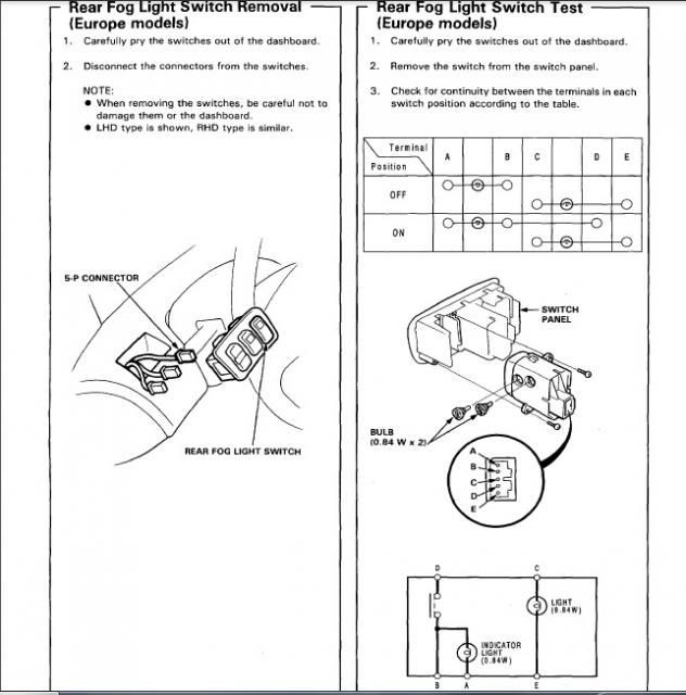
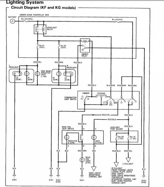
Not sure this will be exactly what you need as I am a bit uncertain about the fog light circuit. I expected this to be a latching switch but it isn't. In other words the wires connected by operation of the switch are only connected whilst the switch is pressed. The signal must operate a latching relay that keeps the power on while required. However, I can tell you which pins are connected.
Assuming that Pin 1 is at the top (which is central to the switch body) - Red / Blue wire
Pin 2 - Black
Pin 3 - Red / Black
Pin 4 - Blue / White
Pin 5 - Red
Pins 1 & 2 and pins 3 & 5 make a circuit whilst the bulbs are in place. Pins 1 & 4 make a circuit whilst the switch is pressed.
Therefore (and I cant guarantee this so don't blame me if you blow fuses


) I believe that Pin 1 is the feed to the relay. Pin 2 is the earth from 'switch on' bulb, Pins 3 & 5 are the switch illumination (from your sidelight circuit) Pin 4 is the power from the ignition. I hope that's of some help
@gordonlear.