Congratulations to vtecmec for winning May/June's Lude Of The Month, with his DIY Turbo BB1 build.

>>> Click Here For Profile <<<

Image

Mystery Vac Line

Engine/Gearbox questions and discussion
User avatar
Vtecmec
LotM Winner
Posts: 5490
Joined: Fri Aug 06, 2010 5:43 pm
My Generation: 4G
XBOX GamerTag: vtecmec
Location: East Midlands
Has thanked: 149 times
Been thanked: 441 times

Mystery Vac Line

Post by Vtecmec » Sun Jul 21, 2013 5:05 pm

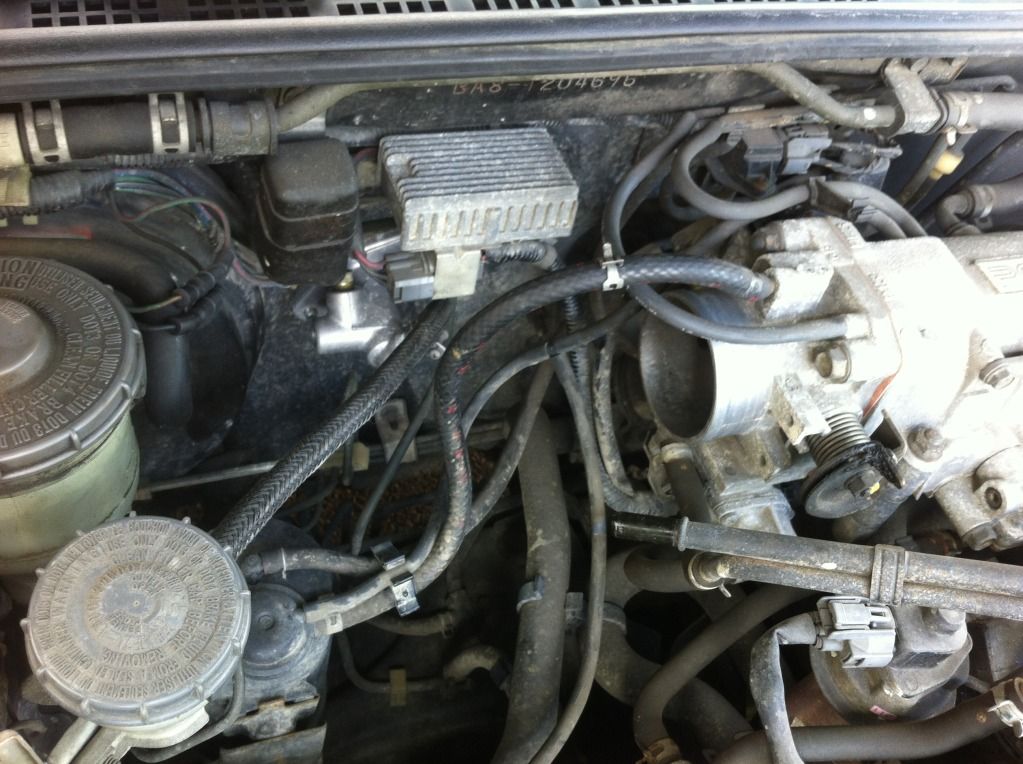
Does anyone know, or can they look where this vac line goes to at the other end?

Image

I can't find reference to it in the manual or any of the supplements. :? I think it might just t into another vac line as I have no loose ends, but not sure?

Thanks in advance.

User avatar
wurlycorner
Ye are glad to be dead, RIGHT?
Posts: 21493
Joined: Sat May 19, 2012 3:33 pm
My Generation: 4G
Location: Chelmsford, Essex
Has thanked: 2481 times
Been thanked: 306 times

Post by wurlycorner » Sun Jul 21, 2013 5:36 pm

Which line are you talking about? I can see 2 vacuum lines in that pic that aren't connected to anything? (1 top middle, 1 middle left).

What's the other end of the vac line connected to? I did a thread about some vac lines on my ludes a while ago, had variouspics of vac lines on a ukdm and jdm because I noticed they weren't the same and wanted to check that was right (it is). If you Do a search in my posts, should find it? That might help answer the question?

User avatar
Vtecmec
LotM Winner
Posts: 5490
Joined: Fri Aug 06, 2010 5:43 pm
My Generation: 4G
XBOX GamerTag: vtecmec
Location: East Midlands
Has thanked: 149 times
Been thanked: 441 times

Post by Vtecmec » Sun Jul 21, 2013 6:29 pm

Sorry, it's the one connected to the (heater device?) in the middle, that vanishes up out of the picture, where is the other end supposed to go? Just checked the entire car referencing the service manual, but this is flapping around with nowhere to go and I can find no reference to it. :?

I'll have search after my tea.

DaveyBa8
Supporter 2016
Posts: 547
Joined: Sun Apr 14, 2013 5:21 pm
My Generation: 4G
XBOX GamerTag: DaveyRocket172
Location: Ireland, Donegal
Been thanked: 1 time

Post by DaveyBa8 » Sun Jul 21, 2013 6:48 pm

there you go man

Image

DaveyBa8
Supporter 2016
Posts: 547
Joined: Sun Apr 14, 2013 5:21 pm
My Generation: 4G
XBOX GamerTag: DaveyRocket172
Location: Ireland, Donegal
Been thanked: 1 time

Post by DaveyBa8 » Sun Jul 21, 2013 6:59 pm

oh yea and that does a full loop right around to that black circle looking thing with the grey plug, to the right of the map sensor.

ran outside there and found the remains on the old lude.
Image

User avatar
Vtecmec
LotM Winner
Posts: 5490
Joined: Fri Aug 06, 2010 5:43 pm
My Generation: 4G
XBOX GamerTag: vtecmec
Location: East Midlands
Has thanked: 149 times
Been thanked: 441 times

Post by Vtecmec » Sun Jul 21, 2013 7:06 pm

Thanks Davey, now I am confused.

I'd found an old pic of the car showing it going to the same spot and assumed it was incorrect, but when checking page 11-3 of the VTEC supplement, that should go to the EVAP cannister at that end and the purge control solenoid at the other? Your EVAP is piped into the general vacuum via a t piece, which again is different than the manual.

Image

:? :? :?

DaveyBa8
Supporter 2016
Posts: 547
Joined: Sun Apr 14, 2013 5:21 pm
My Generation: 4G
XBOX GamerTag: DaveyRocket172
Location: Ireland, Donegal
Been thanked: 1 time

Post by DaveyBa8 » Sun Jul 21, 2013 7:18 pm

mmm, its number 13 on the sheet your looking at? the bypass control diaphragm that vac line (13) then goes to the bypass control solenoid. my EVAP T piece as i remember goes straight to the intake mani, and then off to intake control solenoid box so according to the sheet number 8 and you see with the dotted lines is the T piece. looks ok to me man. i might have a few more pics if your stuck :)

actully yea i see the confusion now :o but thats where i goes man, that purge solenoid valve is the confusion

User avatar
Vtecmec
LotM Winner
Posts: 5490
Joined: Fri Aug 06, 2010 5:43 pm
My Generation: 4G
XBOX GamerTag: vtecmec
Location: East Midlands
Has thanked: 149 times
Been thanked: 441 times

Post by Vtecmec » Sun Jul 21, 2013 7:28 pm

No, not 13, but number 3. According to that EVAP small top pipe should lead to the pipe pictured, and then onto the purge control solenoid. Number 8 (dotted line) is not a t-piece in the diagram, but carries on under the intake pipe and wraps round to the left port on the far side of the throttle body.

DaveyBa8
Supporter 2016
Posts: 547
Joined: Sun Apr 14, 2013 5:21 pm
My Generation: 4G
XBOX GamerTag: DaveyRocket172
Location: Ireland, Donegal
Been thanked: 1 time

Post by DaveyBa8 » Sun Jul 21, 2013 7:29 pm

heres exactly where the EVAP lines go, one to throttle body, one directly behind trottle body on intake mani, and if you look at the first pic i posted one goes to a hard line connected beside fuel lines.

so yea you where right all along and my pic conforms it there for ya it just loops around, head scratching stuff lol

Image

DaveyBa8
Supporter 2016
Posts: 547
Joined: Sun Apr 14, 2013 5:21 pm
My Generation: 4G
XBOX GamerTag: DaveyRocket172
Location: Ireland, Donegal
Been thanked: 1 time

Post by DaveyBa8 » Sun Jul 21, 2013 7:37 pm

yea but that pic you posted is number 13 thats the bypass that controls the coolant for the heatermatrix. you cant see number 3 in your pic. i think that diagram is abit off as i dont even no if we have a purge control solenoid :shock:

am so confused now to, but thats where EVAP lines go and thats where the diagram on the water line goes, it just loops lol

Post Reply

Return to “Engine / GearBox”