Congratulations to vtecmec for winning May/June's Lude Of The Month, with his DIY Turbo BB1 build.
>>> Click Here For Profile <<<

>>> Click Here For Profile <<<
Steering Column Top Cowl Foul.
-
wurlycorner

- Ye are glad to be dead, RIGHT?
- Posts: 21224
- Joined: Sat May 19, 2012 3:33 pm
- My Generation: 4G
- Location: Chelmsford, Essex
- Has thanked: 1968 times
- Been thanked: 240 times
-
NafemanNathan
- LotM Winner
- Posts: 20144
- Joined: Sun Aug 08, 2010 9:37 pm
- My Generation: 0G
- Location: Yeovil, Somerset
- Has thanked: 8 times
- Been thanked: 122 times

-
Lude-dude

- Moderator
- Posts: 2181
- Joined: Tue Aug 03, 2010 10:39 pm
- My Generation: 5G
- XBOX GamerTag: Vtec Junky
- PSN GamerTag: Rob7niner
- Has thanked: 3 times
- Been thanked: 3 times
the ecu & gauges
possibly they removed the dash to wire it all
not that I would..
possibly they removed the dash to wire it all
not that I would..

H22a5 UKDM 2.2 VTI 244Bhp 180lbs/ft Crower stage 2
http://www.ludegeneration.co.uk/profile ... t3211.html
-
NafemanNathan
- LotM Winner
- Posts: 20144
- Joined: Sun Aug 08, 2010 9:37 pm
- My Generation: 0G
- Location: Yeovil, Somerset
- Has thanked: 8 times
- Been thanked: 122 times
-
wurlycorner
- Ye are glad to be dead, RIGHT?
- Posts: 21224
- Joined: Sat May 19, 2012 3:33 pm
- My Generation: 4G
- Location: Chelmsford, Essex
- Has thanked: 1968 times
- Been thanked: 240 times
They've also drokked about running wires for the stereo and to the battery, done something on the switch panels on the rhs of the steering wheel and it looks like they've done something to the loom around the ECU as well?
So who knows that they've actually had out/been up to?!
So who knows that they've actually had out/been up to?!
--
Iain.
Iain.
Super Secret 1G (not really super secret!)
-
rob quilter

- Supporter 2014
- Posts: 5331
- Joined: Mon Aug 09, 2010 1:40 pm
- My Generation: 5G
- PSN GamerTag: robquilter
- Location: Derby
The dash is quite tight to make it fit flush/ as far back as it will go. Check for a gap at the back of the dash (top and sides). If it has been removed then fitted back incorrectly, it could be your issue.
PERFORMANCE PARTS FOR JAPANESE CARS - http://WWW.TOKYOSQUAD.COM
FOLLOW US ON FACEBOOK - http://WWW.FACEBOOK.COM/TOKYOSQUAD
FOLLOW US ON FACEBOOK - http://WWW.FACEBOOK.COM/TOKYOSQUAD
-
NafemanNathan
- LotM Winner
- Posts: 20144
- Joined: Sun Aug 08, 2010 9:37 pm
- My Generation: 0G
- Location: Yeovil, Somerset
- Has thanked: 8 times
- Been thanked: 122 times
Cheers Rob 

What's wrong with the wiring to the battery? There's nothing wrong with the switch panel to the right of the steering wheel And the loom is fine and everything works as it should
Iain, am I detecting anger at the fact I bought a 5th gen?wurlycorner wrote:They've also drokked about running wires for the stereo and to the battery, done something on the switch panels on the rhs of the steering wheel and it looks like they've done something to the loom around the ECU as well?
So who knows that they've actually had out/been up to?!
What's wrong with the wiring to the battery? There's nothing wrong with the switch panel to the right of the steering wheel
-
NafemanNathan
- LotM Winner
- Posts: 20144
- Joined: Sun Aug 08, 2010 9:37 pm
- My Generation: 0G
- Location: Yeovil, Somerset
- Has thanked: 8 times
- Been thanked: 122 times
So the dash is exactly where it should be. No gaps and it's fixed solid.
But I've got a few suspicions as to what it is and I've found that the steering column is adjustable, but I need to be able to slide the outer shaft up the inner shaft towards me.
Any idea if that's possible?
Does/can anyone take a picture of underneath the steering column and the lower mount and also the universal joint without the shroud on please?
Edit:
This is the area in question...
Last edited by NafemanNathan on Fri Mar 28, 2014 8:22 pm, edited 1 time in total.
-
NafemanNathan
- LotM Winner
- Posts: 20144
- Joined: Sun Aug 08, 2010 9:37 pm
- My Generation: 0G
- Location: Yeovil, Somerset
- Has thanked: 8 times
- Been thanked: 122 times
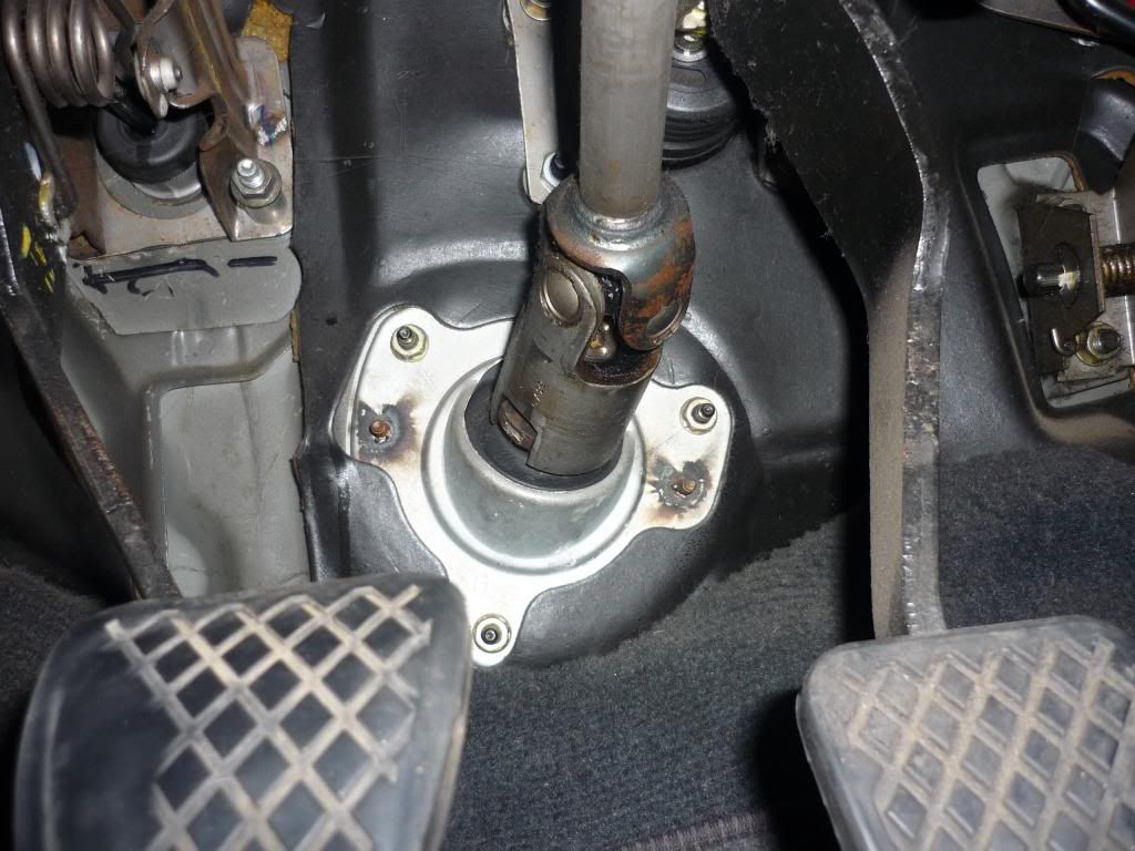
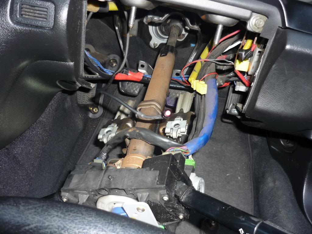
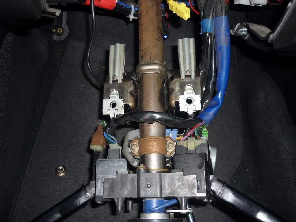
So first of all the SRS has been removed and (I assume) an adapter for the horn has been made up...
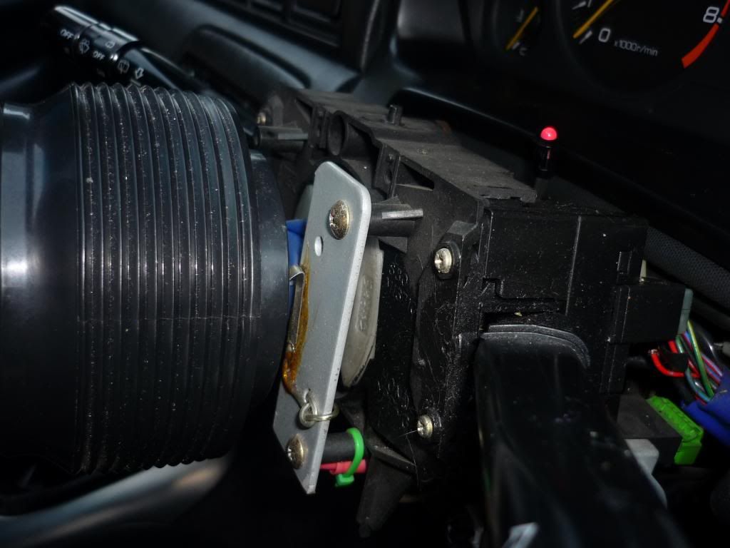
The universal joint looks fine. Although there is no shroud around it, so there's a chance it's been tinkered with...
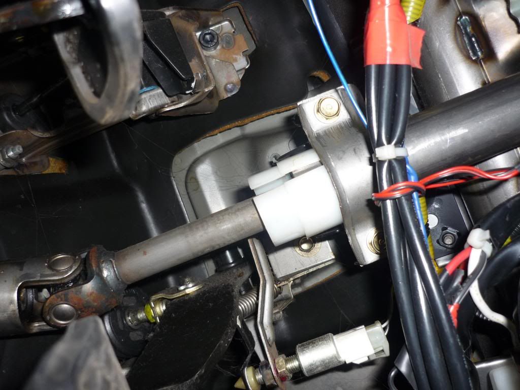
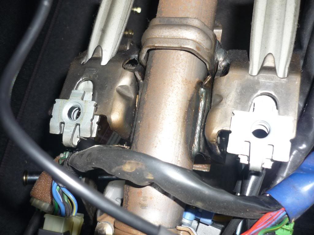
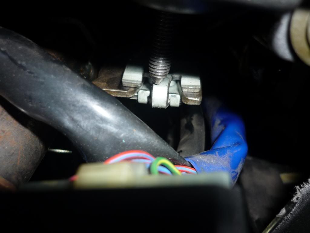
But when looking at the steering column I noticed that this white nylon shim looked like it had slipped...
Surely it should be fully clamped...
I loosened the clamp and tried to slide it up, but it's actually keyed in...
This tab...
Goes into this hole...
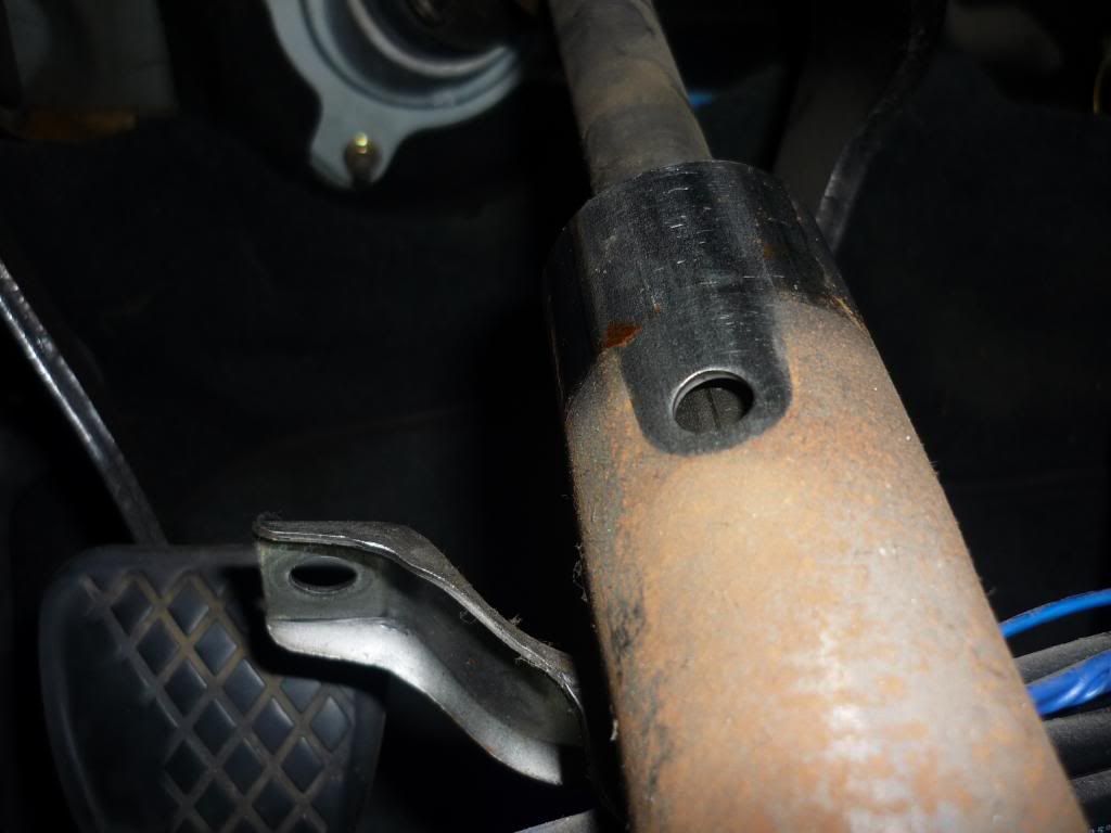
So it was in the correct position in relation to the outer shaft...
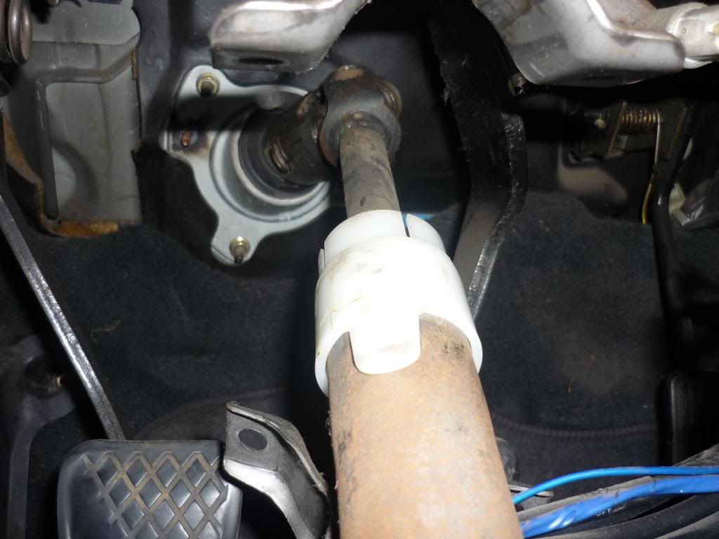
But I still feel the outer shaft along with the white nylon shim need to slide upwards.
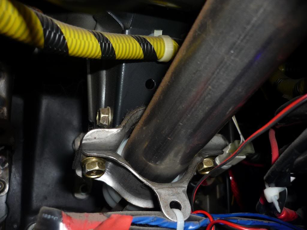
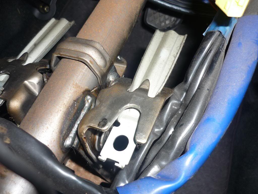
Also if it was possible to slide up the adjustment at the top end would be made here with loosening these nuts...
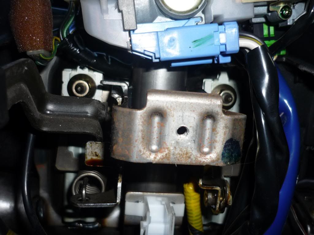
After I undid those nuts and lowered the whole assembly you can see where the adjustment would be made...
This was as they were...
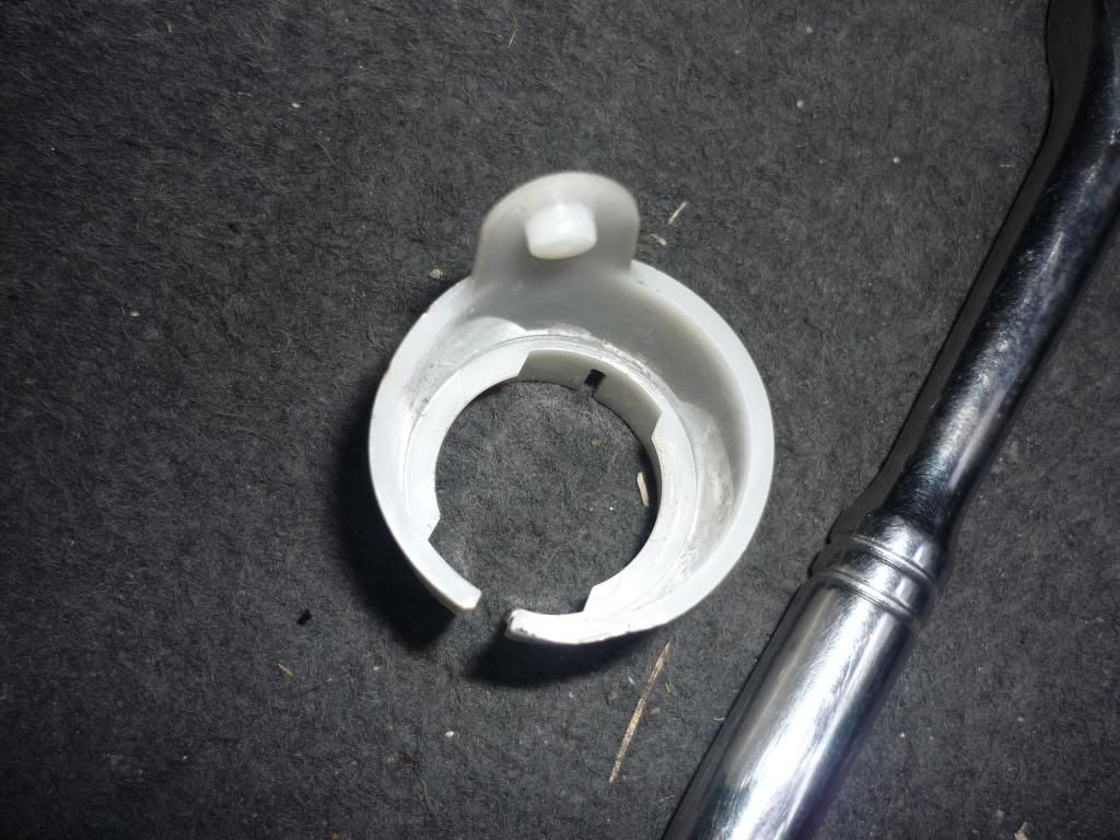
You can remove the top "spacer", and the long slider is kind of jammed in...
The two interlock together like this...
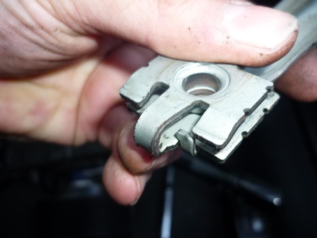
I was able to assemble and slide them so that the top washer was this far in (I forgot to take a picture of when they were actually in position together)...
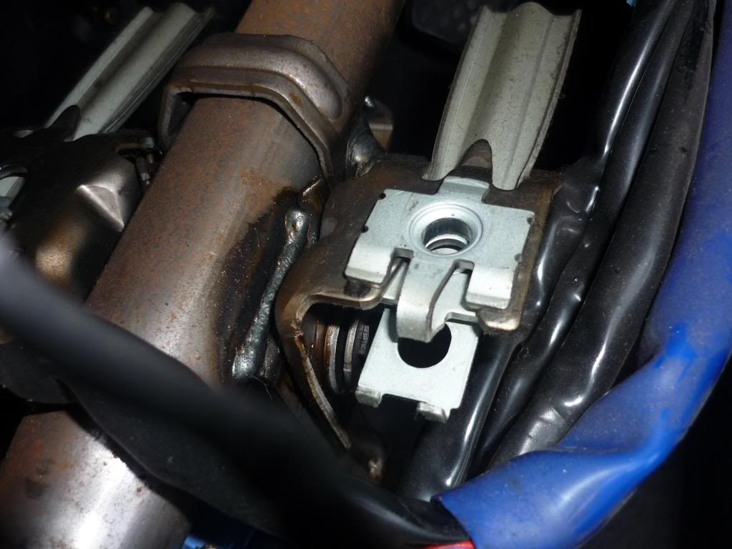
So I reckon there's about 2cm adjustment to be had, but when offering the whole assembly back up the holes fall short of the studs...
So basically, if I was able to slide the outer shaft up about 2cm it would mean that white nylon shim is fully in the clamp and it'd solve my top cowl issue.
So how do I achieve that? ...
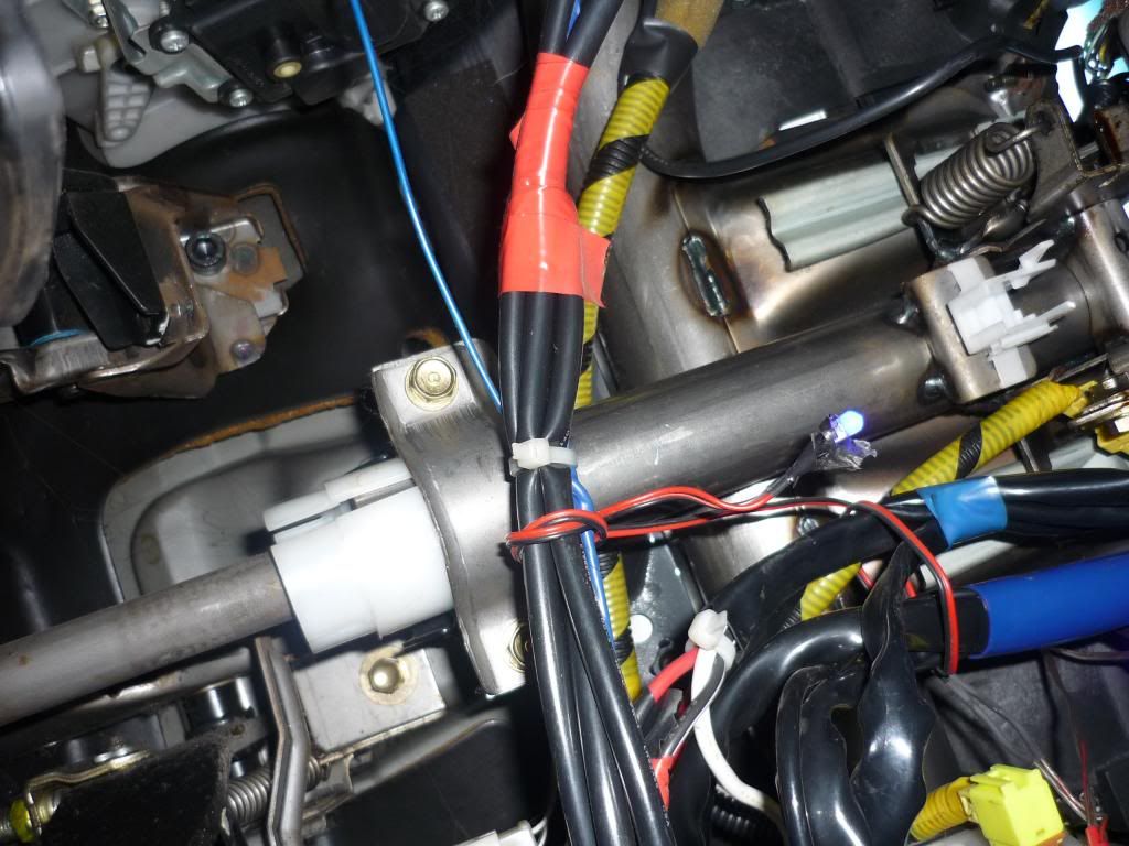
This is the bearing at the end of the outer shaft (The inner shaft on the left goes to the universal joint)...
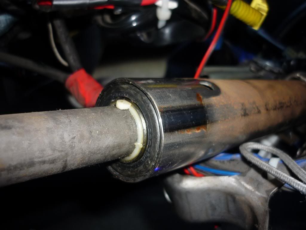
There's also about 2cm of inner shaft that can be taken up if the outer shaft was to slide up (Where the blue electrical tape is)...
Any ideas? Is it just brute force or a nylon hammer on the bearing end of the outer shaft required to slide it up?
The universal joint looks fine. Although there is no shroud around it, so there's a chance it's been tinkered with...
But when looking at the steering column I noticed that this white nylon shim looked like it had slipped...
Surely it should be fully clamped...
I loosened the clamp and tried to slide it up, but it's actually keyed in...
This tab...
Goes into this hole...
So it was in the correct position in relation to the outer shaft...
But I still feel the outer shaft along with the white nylon shim need to slide upwards.
Also if it was possible to slide up the adjustment at the top end would be made here with loosening these nuts...
After I undid those nuts and lowered the whole assembly you can see where the adjustment would be made...
This was as they were...
You can remove the top "spacer", and the long slider is kind of jammed in...
The two interlock together like this...
I was able to assemble and slide them so that the top washer was this far in (I forgot to take a picture of when they were actually in position together)...
So I reckon there's about 2cm adjustment to be had, but when offering the whole assembly back up the holes fall short of the studs...
So basically, if I was able to slide the outer shaft up about 2cm it would mean that white nylon shim is fully in the clamp and it'd solve my top cowl issue.
So how do I achieve that?
This is the bearing at the end of the outer shaft (The inner shaft on the left goes to the universal joint)...
There's also about 2cm of inner shaft that can be taken up if the outer shaft was to slide up (Where the blue electrical tape is)...
Any ideas? Is it just brute force or a nylon hammer on the bearing end of the outer shaft required to slide it up?